


. . . . .
SYSTEM CONTROL MODULE
Interrupt Vector Address Register Level 31–0
www.digiembedded.com 175
. . . . . . . . . . . . . . . . . . . . . . . . . . . . . . . . . . . . . . . . . . . . . . . . . . . . . . . . . . . . . . . . . . . . . . . . . . . . . . . . . .
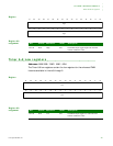
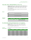
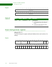
Interrupt Vector Address Register Level 31–0
Addresses: A090 00C4 (level 0) / 00C8 / 00CC / 00D0 / 00D4 / 00D8 / 00DC / 00E0 /
00E4 / 00E8 / 00EC / 00F0 / 00F4 / 00F8 / 00FC / 0100 / 0104 / 0108 / 010C /
0110 / 0114 / 0118 / 011C / 0120 / 0124 / 0128 / 012C / 0130 / 0134 / 0138 /
013C / 0140 (level 31)
The Interrupt Vector Address register configures the Interrupt vector address for
each interrupt level source.
Register
Register bit
assignment
. . . . . . . . . . . . . . . . . . . . . . . . . . . . . . . . . . . . . . . . . . . . . . . . . . . . . . . . . . . . . . . . . . . . . . . . . . . . . . . . . .
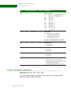
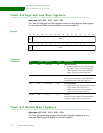
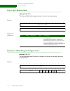
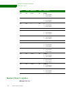
Int (Interrupt) Config (Configuration) 31–0 registers
Addresses: A090 0144 / 0148 / 014C / 0150 / 0154 / 0158 / 015C / 0160
Each Interrupt Configuration register is 8 bits in length, and programs each
interrupt configuration for each priority level.
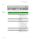
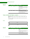
Individual
register mapping
This table shows how the 32 individual 8-byte registers are mapped in the eight 32-
bit registers.
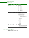
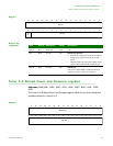
13121110987654321015 14
31 29 28 27 26 25 24 23 22 21 20 19 18 17 1630
Interrupt vector address register value (IVARV)
Interrupt vector address register value (IVARV)
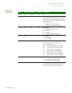
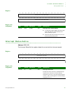
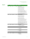
Bits Access Mnemonic Reset Description
D31:00 R/W Int Vec Adr 0x0 Interrupt Vector Address register
Interrupt vector address register bits.
Register [31:24] [23:16] [15:08] [07:00]
A090 0144 Int Config 0 Int Config 1 Int Config 2 Int Config 3
A090 0148 Int Config 4 Int Config 5 Int Config 6 Int Config 7
A090 014C Int Config 8 Int Config 9 Int Config 10 Int Config 11
A090 0150 Int Config 12 Int Config 13 Int Config14 Int Config 15
A090 0154 Int Config 16 Int Config 17 Int Config 18 Int Config 19
A090 0158 Int Config 20 Int Config 21 Int Config 22 Int Config 23