. . . . .
MEMORY CONTROLLER
Static memory read: Timing and parameters
www.digiembedded.com 211
. . . . . . . . . . . . . . . . . . . . . . . . . . . . . . . . . . . . . . . . . . . . . . . . . . . . . . . . . . . . . . . . . . . . . . . . . . . . . . . . . .
Static memory read: Timing and parameters
This section shows static memory read timing diagrams and parameters.
External memory
read transfer with
zero wait states
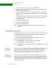
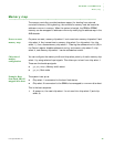
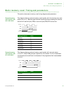
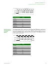
This diagram shows an external memory read transfer with the minimum zero wait
states (
WA IT RD =0). Maximum performance is achieved when accessing the external
device with load multiple (LDM) or store multiple (STM) CPU instructions.
External memory
read transfer with
two wait states
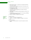
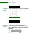
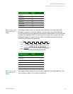
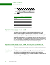
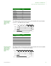
This diagram shows an external memory read transfer with two wait states
(
WA IT RD =2). Seven AHB cycles are required for the transfer, five for the standard
read access and an additional two because of the programmed wait states added
(WA ITR D).
Timing parameter Value
WAITRD 0
WAITOEN 0
WAITPAGE N/A
WAITWR N/A
WAITWEN N/A
WAITTURN N/A
A
D(A)
clk_out
addr
data
cs[n]
st_oe_n
Timing parameter Value
WAITRD 2
WAITOEN 0
WAITPAGE N/A
WAITWR N/A
A
D(A)
addr
data
cs[n]
st_oe_n
clk_out


