


. . . . .
MEMORY CONTROLLER
StaticMemory Configuration 0–3 registers
www.digiembedded.com 253
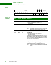
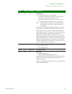
D07 R/W PB Byte lane state
0 For reads, all bits in
byte_lane[3:0] are high.
For writes, the respective active bits in
byte_lane[3:0] are low
(reset value for chip select 0, 2, and 3 on
reset_n).
1 For reads, the respective active bits in
byte_lane[3:0] are low.
For writes, the respective active bits in
byte_lane[3:0] are low.
Note: Setting this bit to 0 disables the write enable signal.
WE_n
will always be set to 1 (that is, you must use byte lane
select signals).
The byte lane state bit (PB) enables different types of memory to
be connected. For byte-wide static memories, the
byte_lane[3:0]
signal from the memory controller is usually connected to WE_n
(write enable). In this case, for reads, all byte_lane[3:0] bits must be
high, which means that the byte lane state bit must be low.
16-bit wide static memory devices usually have the
byte_lane[3:0]
signals connected to the
nUB and nLB (upper byte and lower byte)
signals in the static memory. In this case, a write to a particular byte
must assert the appropriate
nUB or nLB signal low. For reads, all
nUB and nLB signals must be asserted low so the bus is driven. In
this case, the byte lane state must be high.
D06 R/W PC Chip select polarity
0 Active low chip select
1 Active high chip select
D05:04 N/A Reserved N/A (do not modify)
D03 R/W PM Page mode
0 Disabled (reset on
reset_n)
1 Async page mode enabled (page length four)
In page mode, the memory controller can burst up to four external
accesses. Devices with asynchronous page mode burst four or
higher are supported.
Asynchronous page mode burst two devices are not supported and
must be accessed normally.
Bits Access Mnemonic Description