


. . . . .
AES DATA ENCRYPTION/DECRYPTION MODULE
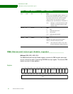
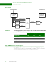
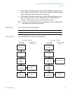
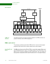
AES DMA buffer descriptor
www.digiembedded.com 357
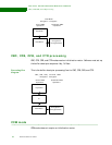
AES buffer
descriptor
diagram
Field definitions follow.
Source address
[pointer]
The source address pointer identifies the starting location of the source data. The
source address can be aligned to any byte boundary.
Note:
Optimal performance is achieved when the source address is aligned on a
word boundary.
Source buffer
length
The source buffer length indicates the number of bytes to be read from the source.
After completing the transfer, the DMA controller updates this field with the actual
number of bytes that were moved. This is useful for debugging error conditions or
determining the number of bytes transferred before the DONE signal was asserted.
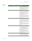
Destination buffer
length
The destination buffer length indicates the number of bytes to be written to the
destination. This field should be identical to the source buffer length for all modes —
with the exception of CCM — when the authentication code is being generated or a
key is being expanded.
Destination
address [pointer]
The description address pointer field identifies the starting location of the source
data’s destination; that is, to where the source data needs to be moved. The
destination address must be word-aligned.
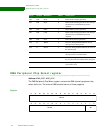
AES control
Destination address
Source buffer length
AES control
Source address
8
FILW Reserved
Destination buffer length
31 30 29 28 16 15 0
OFFSET + 0
OFFSET + C
OFFSET +
OFFSET + 4
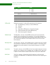
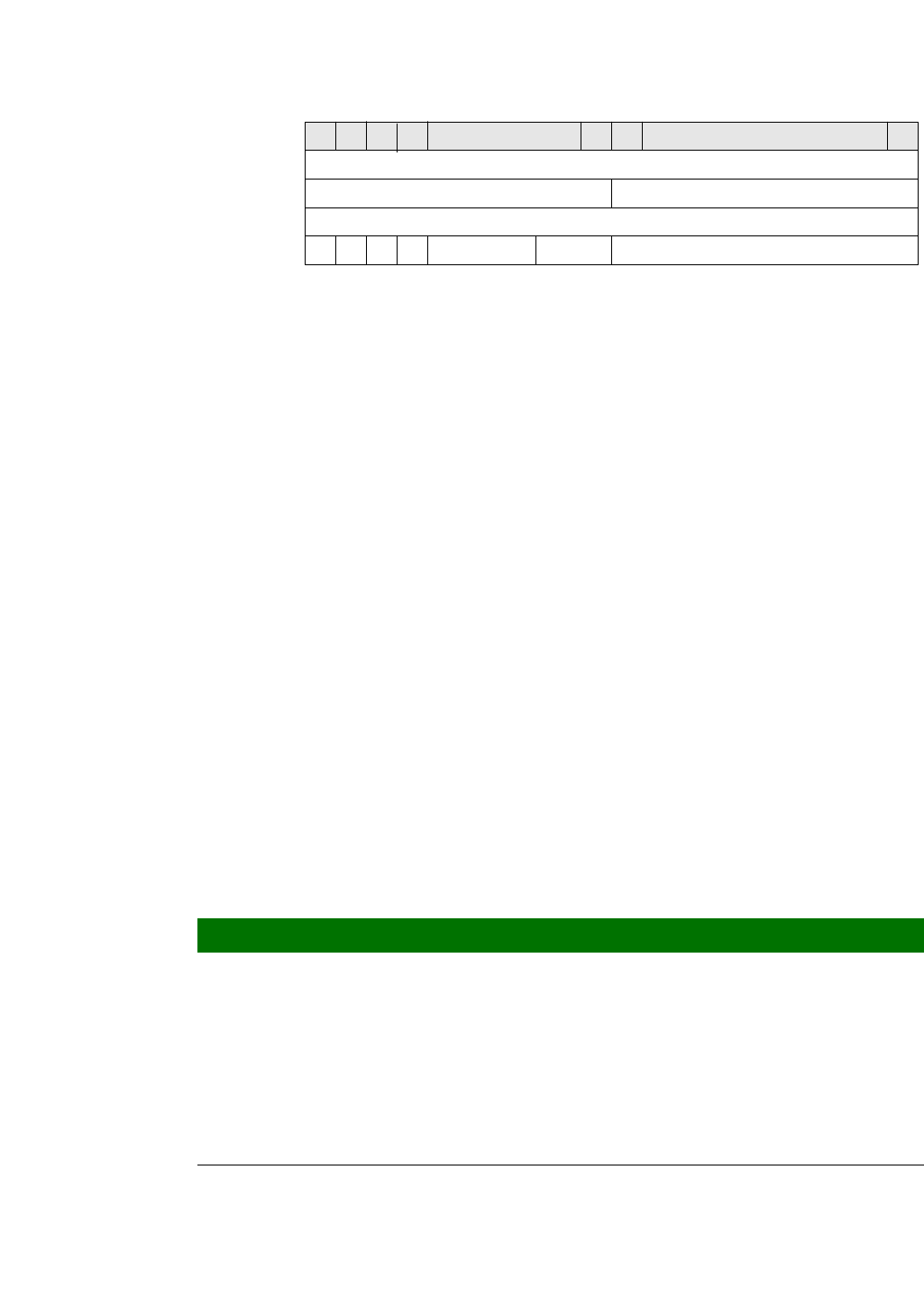
AES Op
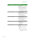
Bits Used for Values
[2:0] Encryption mode select 000 CBC
001 CFB
010 OFB
011 CTR
100 ECB
101 CCM
111 Key expand mode, which allows a key to be
expanded by the hardware key expander and
written back to system memory
[3] Encryption/decryption select 0 Encryption
1 Decryption