. . . . .
I/O HUB MODULE
Transmit DMA example
www.digiembedded.com 367
HDLC
SPI
Not applicable.
. . . . . . . . . . . . . . . . . . . . . . . . . . . . . . . . . . . . . . . . . . . . . . . . . . . . . . . . . . . . . . . . . . . . . . . . . . . . . . . . . .
Transmit DMA example
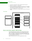
After the last buffer in the data packet has been placed in system memory and the
buffer descriptors have been configured, the data packet is ready to be transmitted.
The CPU configures the module DMA TX buffer descriptor pointer, TXBDP (see
“[Module] DMA TX Buffer Descriptor Pointer” on page 381), and then sets the channel
enable bit in the DMA Control register.
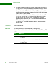
Process The DMA controller starts the process to read the buffer descriptor and buffer data
from system memory using the AHB master. The DMA controller follows this process:
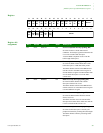
1 Reads the first buffer descriptor, as pointed to by the TX buffer descriptor
pointer and INDEX.
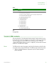
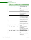
Bits Description
15:7 Reserved
6:5 01 HDLC frame close, bits 3:0 indicate the close condition
bit 4: The last byte is less than 8 bits
bit 3: Receiver overflow, should never occur in a properly configured system
bit 2: Invalid CRC found at end of frame
bit 1: Valid CRC found at end of frame
bit 0: Abort condition found
11 match character found
bit 4: Match character 4
bit 3: Match character 3
bit 2: Match character 2
bit 1: Match character 1
bit 0: Match character 0
00 Other close event
bit 2: Buffer gap timer expired
bit 1: Software-initiated buffer close


