. . . . .
SYSTEM CONTROL MODULE
AHB Error Detect Status 1
www.digiembedded.com 159
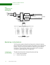
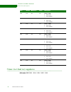
Channel
allocation
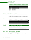
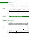
This is how the channels are assigned in the four registers:
Register
Register bit
assignment
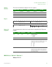
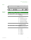
This table shows the bit definition for each channel, using data bits [07:00] as the
example.
. . . . . . . . . . . . . . . . . . . . . . . . . . . . . . . . . . . . . . . . . . . . . . . . . . . . . . . . . . . . . . . . . . . . . . . . . . . . . . . . . .
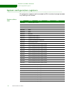
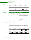
AHB Error Detect Status 1
Address: A090 0018
Register name [31:24] [23:16] [15:08] [07:00]
BRC0 Channel 0 Channel 1 Channel 2 Channel 3
BRC1 Channel 4 Channel 5 Channel 6 Channel 7
BRC2 Channel 8 Channel 9 Channel 10 Channel 11
BRC3 Channel 12 Channel 13 Channel 14 Channel 15
HMSTR
13121110987654321015 14
31 29 28 27 26 25 24 23 22 21 20 19 18 17 1630
Channel 0, 4, 8, or 12 Channel 1, 5, 9, or 13
Channel 2, 6, 10, or 14
Channel 3, 7, 11, or 15
CEB Rsvd BRF
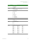
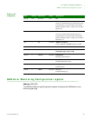
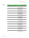
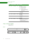
Bits Access Mnemonic Reset Description
D07 R/W CEB 0x0 Channel enable bit
0 Disabled
1 Enabled
D06 N/A Reserved N/A N/A
D05:04 R/W BRF 0x0 Bandwidth reduction field
Program the weight for each AHB bus master. Used
to limit access to the round robin scheduler.
00 100%
01 75%
10 50%
11 25%
D03:00 R/W HMSTR 0x0 hmaster
Program a particular AHB bus master number here.
Note that a particular master an be programmed to
more than one channel.


