


. . . . .
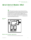
SERIAL CONTROL MODULE: HDLC
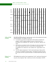
DPLL operation: Adjustment ranges and output clocks
www.digiembedded.com 419
DPLL-tracked bit
cell boundaries
The DPLL counter normally counts by 16 but if a transition occurs earlier or later than
expected, the count is modified during the next count cycle.
If the transition occurs earlier than expected, the bit cell boundaries are early
with respect to the DPLL-tracked cell boundaries and the count is shortened by
either one or two counts.
If the transition occurs later than expected, the bit cell boundaries are late
with respect to the DPLL-tracked bit cell boundaries and the count is
lengthened by either one or two counts.
How far off the DPLL-tracked bit cell boundaries are determines whether the count
is adjusted by one or two. This tracking allows for minor differences in the transmit
and receive clock frequencies.
NRZ and NRZI
data encoding
With NRZ and NRZI data encoding, the DPLL counter runs continuously and adjusts
after every receive data transition.
Because NRZ encoding does not guarantee a minimum density of transitions, the
difference between the sending data rate and the DPLL output clock rate must be
very small, and depends on the longest possible run of zeros in the received frame.
NRZI encoding guarantees at least one transition every six bits (with the inserted
zeroes). Because the DPLL can adjust by two counts every bit cell, the maximum
difference between the sending data rate and the DPLL output clock rate is 1/48
(~2%).
Biphase data
encoding
With biphase data encoding, the DPLL works in multiple-access conditions where
there may not be flags on the idle line. The DPLL properly generates an output clock
based on the first transition in the leading zero of an opening flag. Similarly, the DPLL
requires only the completion of the closing flag to provide the extra two clocks to the
receiver to properly assemble the data.
In biphase-level mode, this means the transition that defines the last zero of
the closing flag.
In the biphase-mark and biphase-space modes, this means the transition that
defines the end of the last zero of the closing flag.
. . . . . . . . . . . . . . . . . . . . . . . . . . . . . . . . . . . . . . . . . . . . . . . . . . . . . . . . . . . . . . . . . . . . . . . . . . . . . . . . . .
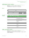
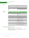
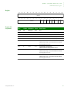
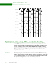
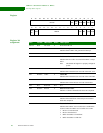
DPLL operation: Adjustment ranges and output clocks
This figure shows the adjustment ranges and output clock for the different DPLL
modes of operation: