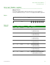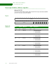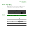
ANALOG-TO-DIGITAL CONVERTER (ADC) MODULE
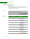
ADC Configuration register
476 Hardware Reference NS9215
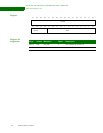
Register
Register bit
assignment
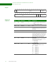
13121110987654321015 14
31 29 28 27 26 25 24 23 22 21 20 19 18 17 1630
Reserved
Reserved
INTCLR
ADCEN INSTAT
DMAEN SEL
Bit(s) Access Mnemonic Reset Description
D31 R/W ADCEN 0 0 The ADC module is disabled and held in
reset
1 The ADC module is enabled
D30:19 N/A Reserved N/A N/A
D18:16 R INSTAT 0 Interrupt status
Indicates the channel processed at the time of
the interrupt.
D15:5 N/A Reserved N/A N/A
D04 R/W INTCLR 0 Interrupt clear
The ADC module generates an interrupt each
time the ADC generates a new value. This bit
clears the interrupt. The CPU must write a 1,
then a 0 to this bit to clear the interrupt.
D03 R/W DMAEN 0 DMA enable
If set, ADC output data is written to memory
using UART D’s receive DMA.
0DMA disabled
1 DMA enabled
D02:00 R/W SEL 000 ADC channel select
Controls how many channels are active.
000 Channel 0
001 Channels 0-1
010 Channels 0-2
011 Channels 0-3
100 Channels 0-4
101 Channels 0-5
110 Channels 0-6
111 Channels 0-7


