SYSTEM CONTROL MODULE
ISADDR register
176 Hardware Reference NS9215
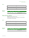
Register bit
assignment
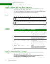
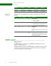
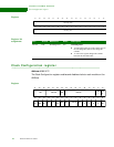
This is how the bits are assigned in each register, using data bits [07:00] as the
example.
. . . . . . . . . . . . . . . . . . . . . . . . . . . . . . . . . . . . . . . . . . . . . . . . . . . . . . . . . . . . . . . . . . . . . . . . . . . . . . . . . .
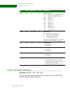
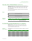
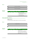
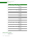
ISADDR register
Address: A090 0164
The ISADDR register provides the current ISADDR value. Read and write to this
register for IRQ interrupts only.
Immediately before the read to the ISADDR register, always perform an extra write
or read to any other internal register to consume an extra clock cycle. Make sure
that the extra access is not optimized away.
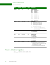
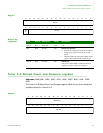
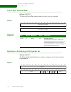
A090 015C Int Config 24 Int Config 25 Int Config 26 Int Config 27
A090 0160 Int Config 28 Int Config 29 Int Config 30 Int Config 31
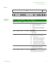
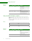
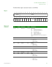
Register [31:24] [23:16] [15:08] [07:00]
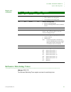
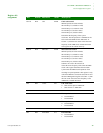
Bits Access Mnemonic Reset Description
D07 R/W IE 0x0 Interrupt enable
0 Interrupt is disabled
1 Interrupt is enabled
D06 R INV 0x0 Invert
0 Do not invert the level of the interrupt source.
1 Invert the level of the interrupt source.
D05 R/W IT 0x0 Interrupt type
0IRQ
1FIQ
If FIQ is programmed, Interrupt must be the highest
priority.
D04:00 R/W ISD 0x0–
0x1F
Interrupt source ID
Assign an interrupt ID to each priority level. See
"Interrupt sources," beginning on page 149, for the
list of interrupt ID numbers.


