SYSTEM CONTROL MODULE
Timer 6–9 High and Low Step registers
172 Hardware Reference NS9215
. . . . . . . . . . . . . . . . . . . . . . . . . . . . . . . . . . . . . . . . . . . . . . . . . . . . . . . . . . . . . . . . . . . . . . . . . . . . . . . . . .
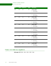
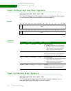
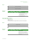
Timer 6–9 High and Low Step registers
Addresses: A090 0098 / 009C / 00A0 / 00A4
The Timer 6–9 High and Low Step registers contain the high and low step registers
for the enhanced PWM features available in timers 6 through 9.
Register
Register bit
assignment
. . . . . . . . . . . . . . . . . . . . . . . . . . . . . . . . . . . . . . . . . . . . . . . . . . . . . . . . . . . . . . . . . . . . . . . . . . . . . . . . . .
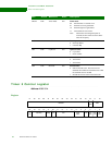
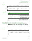
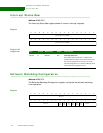
Timer 6–9 Reload Step registers
Addresses: A090 00A8 / 00AC / 00B0 / 00B4
The Timer 6–9 reload Step registers contain the reload step registers for the
enhanced PWM features available in timers 6 through 9.
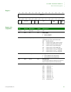
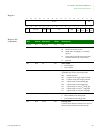
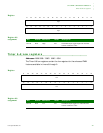
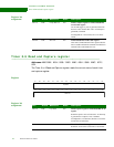
13121110987654321015 14
31 29 28 27 26 25 24 23 22 21 20 19 18 17 1630
Lo
Step
Dir
Hi
Step
Dir
Lo Step
Hi Step
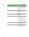
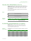
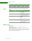
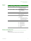
Bits Access Mnemonic Reset Description
D31 R/W Hi Step Dir 0x0 High step direction
0 Subtract the high step value from the original
high register value to increase the high time.
1 Add the high step value to the original high
register value to decrease the high time.
D30:16 R/W Hi Step 0x0 High step
This value is either added or subtracted from the
original high register value once each cycle.
D15 R/W Lo Step Dir 0x0 Low step direction
0 Subtract the low step value from the original low
register value to increase low time 2.
1 Add the low step value to the original low
register value to decrease low time 2.
D14:00 R/W Lo Step 0x0 Low step
This value is either added or subtracted from the
original low register value once each cycle.


