SYSTEM CONTROL MODULE
RTC Module Control register
200 Hardware Reference NS9215
. . . . . . . . . . . . . . . . . . . . . . . . . . . . . . . . . . . . . . . . . . . . . . . . . . . . . . . . . . . . . . . . . . . . . . . . . . . . . . . . . .
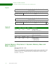
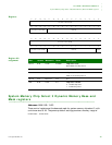
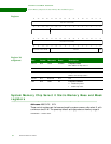
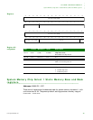
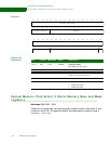
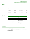
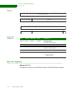
RTC Module Control register
Address: A090 0224
The RTC Module Control register controls the RTC module.
Register
Register bit
assignment
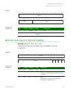
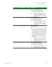
D01 R/W PLTY 0x0 Polarity
0 If level-sensitive, the input source is active high.
If edge-sensitive, generate an interrupt on the rising
edge of the external interrupt.
1 If level-sensitive, the input source is active low. The
level is inverted before sending to the interrupt
controller.
If edge-sensitive, generate an interrupt on the falling
edge of the external interrupt.
D00 R/W LVEDG 0x0 Level edge
0 Level-sensitive interrupt
1 Edge-sensitive interrupt
Bits Access Mnemonic Reset Description
13121110987654321015 14
31 29 28 27 26 25 24 23 22 21 20 19 18 17 1630
Reserved
Reserved
Clk
rdy
int
Standby
mode
Standby
status
Rdy int Int stat
Bits Access Mnemonic Reset Description
D31:05 N/A Reserved N/A N/A
D04 R Standby status 0x0 RTC standby mode status
0 RTC module is in standby mode and cannot be
accessed by the CPU.
1 RTC module is not in standby mode and can be
accessed by the CPU.


