


SYSTEM CONTROL MODULE
Basic PWM function
144 Hardware Reference NS9215
Interrupt enable
Concatenate to up-stream timer/counter; that is, use up-stream
timer/counter’s overflow/underflow output as clock input
Reload enable
Basic PWM function
Enhanced PWM functionality (timers 6–9)
Quadrature decoder function (timer 5)
32-bit or 16-bit operation
16-bit mode
options
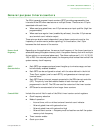
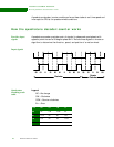
These options are available in 16-bit mode:
Capture mode. Capture the counter value on the rising or falling edge of an
external event and interrupt the CPU.
Compare mode. Interrupt the CPU when the counter value is equal to the
Match register.
. . . . . . . . . . . . . . . . . . . . . . . . . . . . . . . . . . . . . . . . . . . . . . . . . . . . . . . . . . . . . . . . . . . . . . . . . . . . . . . . . .
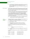
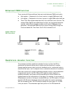
Basic PWM function
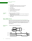
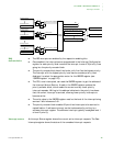
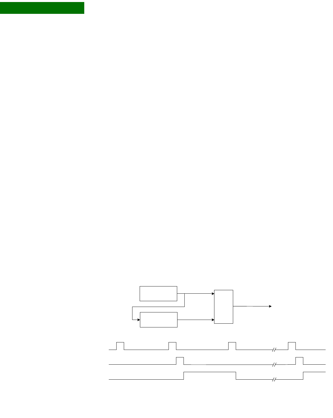
Any of the timer/counters can be configured to provide a basic PWM function. Each
PWM function requires concatenating two timer/counters, resulting in four PWM
outputs. One of the timer/counters controls the pulse width and the other controls
the period. The basic PWM function is output through GPIO through functions
labeled PWM Ch N.
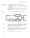
Functional block
diagram
This diagram illustrates the basic PWM function:
Timer/Counter 0
Timer/Counter 1
PWM 0
pulse width control
period control
pwm out 0
pulse width control
period control
pwm out 0