MEMORY CONTROLLER
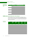
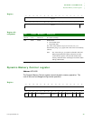
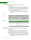
Dynamic Memory Refresh Timer register
236 Hardware Reference NS9215
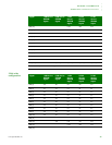
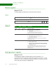
Register bit
assignment
. . . . . . . . . . . . . . . . . . . . . . . . . . . . . . . . . . . . . . . . . . . . . . . . . . . . . . . . . . . . . . . . . . . . . . . . . . . . . . . . . .
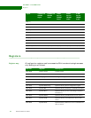
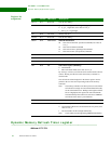
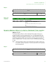
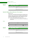
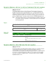
Dynamic Memory Refresh Timer register
Address: A070 0024
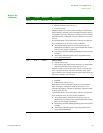
Bits Access Mnemonic Description
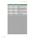
D31:15 N/A Reserved N/A (do not modify)
D14 R/W nRP Sync/Flash reset/power down signal (
dy_pwr_n)
0
dy_pwr_n signal low (reset value on reset_n)
1Set
dy_pwr_n signal high
D13 R/W Not used Always write to 0.
D12:09 N/A Reserved N/A (do not modify)
D08:07 R/W SDRAMInit SDRAM initialization
00 Issue
SDRAM NORMAL operation command (reset value on
reset_n)
01 Issue
SDRAM MODE command
10 Issue
SDRAM PALL (precharge all) command
11 Issue SDRAM NOP (no operation) command
D06 N/A Reserved N/A (do not modify)
D05 R/W Not used Must write 0.
D04:03 N/A Reserved N/A (do not modify)
D02 R/W SR Self-refresh request (
SREFREQ)
0 Normal mode
1 Enter self-refresh mode (reset value on reset_n)
By writing 1 to this bit, self-refresh can be entered under software
control. Writing 0 to this bit returns the memory controller to
normal mode.
The self-refresh acknowledge bit in the Status register must be
polled to discover the current operating mode of the memory
controller.
Note: The memory controller exits from power-on reset with the
self-refresh bit on high. To enter normal functional mode,
set the self-refresh bit low. Writing to this register with the
bit set to high places the register into self-refresh mode.
This functionality allows data to be stored over SDRAM
self-refresh of the ASIC is powered down.
D01 R/W Not used Must write 1.
D00 R/W CE Dynamic memory clock enable
0 Clock enable if idle devices are deasserted to save power (reset
value on
reset_n)
1 All clock enables are driven high continuously.
Note: Clock enable must be high during SDRAM initialization.


