


. . . . .
SYSTEM CONTROL MODULE
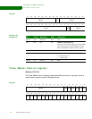
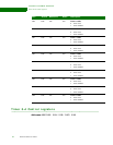
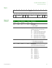
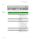
Timer 6–9 Control registers
www.digiembedded.com 169
Register
Register bit
assignment
13121110987654321015 14
31 29 28 27 26 25 24 23 22 21 20 19 18 17 1630
Reserved TM2
TE
Cap Comp
Debug
Int Clr
TCS
Timer
Mode
1
Int
Sel
Up
Down
Bit
Timer
Rel
Enbl
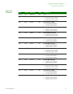
Bits Access Mnemonic Reset Description
D31:18 N/A Reserved N/A N/A
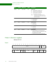
D17:16 R/W TM2 0x0 Timer mode 2
00 Mode as set by timer mode 1
01 PWM mode, using High, Low, and Step
registers
10 Clock mode, toggle the timer output at the
terminal count to create a clock output
11 Reserved
D15 R/W TE 0x0 Timer enable
0 Timer disabled
1 Timer enabled
D14:12 R/W Cap Comp 0x0 Capture and compare mode functions
Applicable only when in 16-bit timer mode.
000 Normal operation
001 Compare mode, toggle output on match
010 Compare mode, pulse output on match
011 Capture mode, on input falling edge
100 Capture mode, on input rising edge
101 Capture mode, on every 2
nd
rising edge
110 Capture mode, on every 4
th
rising edge
111 Capture mode, on every 8
th
rising edge
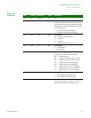
D11 R/W Debug 0x0 Debug mode
0 Timer enabled in CPU debug mode
1 Timer disabled in CPU debug mode
D10 R/W Int Clr 0x0 Interrupt clear
Clears the timer interrupt. Software must write a 1,
then a 0 to this location to clear the interrupt.