


MEMORY CONTROLLER
SDRAM Initialization
226 Hardware Reference NS9215
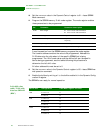
10 Set the SDRAMInit value in the Dynamic Control register to 01 — Issue SDRAM
Mode command.
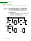
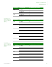
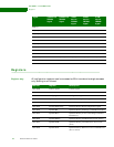
11 Program the SDRAM memory 10-bit mode register. The mode register enables
these parameters to be programmed:
A read transaction from the SDRAM memory programs the mode register.
The transfer address contains the value to be programmed. Address bits
31:28 determine the chip select of the specific SDRAM that is being
programmed. The 10-bit mode value must be shifted left per the specific
device being programmed; see the tables following this procedure to
determine the left shift value.
All other address bits must be set to 0.
12 Set the SDRAMInit value in the Dynamic Control register to 00 — Issue SDRAM nor-
mal operation command.
13 Enable the buffers by writing a 1 to the buffer enable bit in the Dynamic Config-
uration N register.
The SDRAM is now ready for normal operation.
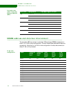
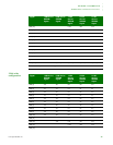
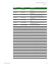
Left-shift value
table: 32-bit wide
data bus SDRAM
(RBC)
Bit Parameter Parameter description
02:00 Burst length
4 for a 32-bit wide external bus
8 for a 16-bit wide external bus
03 Burst type Sequential
06:04 CAS latency Dependent on the SDRAM device and operating
frequency
08:07 Operating mode Standard operation
09 Write burst mode Programmed burst length
Device size Configuration Load Mode register left shift
16M 2 x 1M x 16 11
4 x 2M x 8 12
64M 1 x 2M x 32 12
2 x 4M x 16 12
4 x 8M x 8 13
128M 1 x 4M x 32 12
2 x 8M x 16 13
4 x 16M x 8 14