. . . . .
SERIAL CONTROL MODULE: HDLC
HDLC Clock Divider High
www.digiembedded.com 431
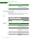
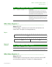
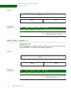
Use the HDLC CLock Divider Low register to set bits 07:00 of the clock divider. This
is the equation for the HDLC clock rate:
Register
Register bit
assignment
. . . . . . . . . . . . . . . . . . . . . . . . . . . . . . . . . . . . . . . . . . . . . . . . . . . . . . . . . . . . . . . . . . . . . . . . . . . . . . . . . .
HDLC Clock Divider High
Address: 9002_911C
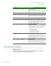
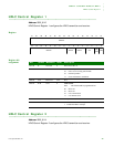
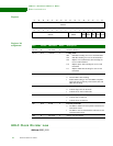
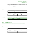
Use the HDLC CLock Divider High register to set bits 14:08 of the clock divider.
Register
HDLC rate (bps) =
29.4912 MHz
16 x (DIV = 1)
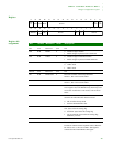
13 12 11 10 9 8 7 6 5 4 3 2 1 015 14
31 29 28 27 26 25 24 23 22 21 20 19 18 17 1630
Not used
Not used
DI VL
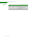
Bits Access Mnemonic Reset Description
D31:08 R Not used 0 Write this field to 0.
D07:00 R/W DIVL 0 Eight LSBs of the divider that generates the HDLC
transmit and receive clock.
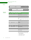
13 12 11 10 9 8 7 6 5 4 3 2 1 015 14
31 29 28 27 26 25 24 23 22 21 20 19 18 17 1630
Not used
Not used
DIVHEN


