SYSTEM CONTROL MODULE
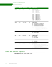
Timer 0-9 Read and Capture register
174 Hardware Reference NS9215
Register bit
assignment
. . . . . . . . . . . . . . . . . . . . . . . . . . . . . . . . . . . . . . . . . . . . . . . . . . . . . . . . . . . . . . . . . . . . . . . . . . . . . . . . . .
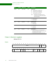
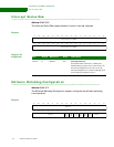
Timer 0-9 Read and Capture register
Addresses: A090 0050 / 0054 / 0058 / 005C / 0060 / 0064 / 0068 / 006C / 0070 /
0074
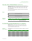
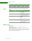
The Timer 0 to 9 Read and Capture register reads the current state of each timer
and capture register.
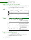
Register
Register bit
assignment
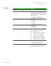
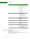
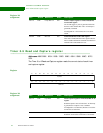
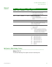
Bits Access Mnemonic Reset Description
D31:16 R/W Comp Rel Cnt 0x0 Timer Compare register or Timer Reload Bits
31:16 Count register
An external toggle or pulse is generated each time
the timer value matches this value. An interrupt is
generated, if enabled.
If configured for a 32-bit timer, bits 31:16 timer
reload.
D15:00 R/W Rel 15:0 0x0 Timer Reload Bits 15:00 Count register
This value is loaded into the Timer register after the
timer is enable and after the terminal count has been
reached if the reload enable bit is set.
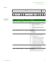
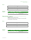
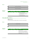
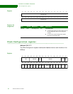
13121110987654321015 14
31 29 28 27 26 25 24 23 22 21 20 19 18 17 1630
Cap Read
Read 15:0
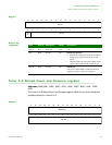
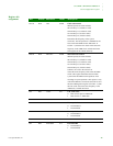
Bits Access Mnemonic Reset Description
D31:16 R/W Cap Read 0x0 Timer Capture register or Timer Read Bits 31:16
register
Reads the capture value of each timer. An interrupt
is generated on a capture event, if enabled.
If configured as a 32-bit timer, then bits 31:16 of the
current state of each timer.
D15:00 R/W Read 15:0 0x0 Timer Read Bits 15:00 register
Reads bits 15:00 of the current state of each timer.


