


. . . . .
ETHERNET COMMUNICATION MODULE
Multicast Address Mask registers
www.digiembedded.com 329
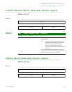
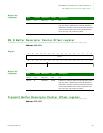
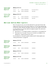
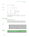
Multicast High
Address Filter
Register #6
Address: A060 0A78
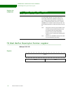
Multicast High
Address Filter
Register #7
Address: A060 0A7C
. . . . . . . . . . . . . . . . . . . . . . . . . . . . . . . . . . . . . . . . . . . . . . . . . . . . . . . . . . . . . . . . . . . . . . . . . . . . . . . . . .
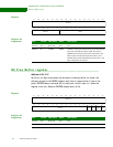
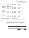
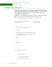
Multicast Address Mask registers
Each of the eight entries in the multicast address filter logic has individual mask
registers that extend the filtering range of each entry. The multicast address mask
for each entry is split between two registers. Each entry has a register that contains
the lower 32 bits of the multicast mask and a separate register that contains the
upper 16 bits of the mask.
Bits are set to 1 in the mask to enable or include that bit in the address filter.
Bits are set to 0 in the mask if they are not included or are disabled in the
address filter. These bits become don’t cares.
For an explanation of the synchronization scheme used for these registers, see
“Clock synchronization” on page 276.
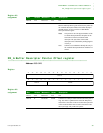
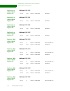
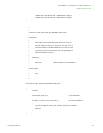
Multicast Low
Address Mask
Register #0
Address: A060 0A80
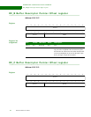
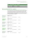
Multicast Low
Address Mask
Register #1
Address: A060 0A84
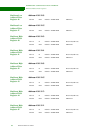
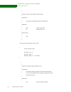
Multicast Low
Address Mask
Register #2
Address: A060 0A88
Multicast Low
Address Mask
Register #3
Address: A060 0A8C
D31:16 R Default = 0x0000 0000 Reserved (read as 0)
D15:00 R/W Default = 0x0000 0000 MFILTH6
D31:16 R Default = 0x0000 0000 Reserved (read as 0)
D15:00 R/W Default = 0x0000 0000 MFILTH7
D31:00 R/W Default = 0x0000 0000 MFMSKL0
D31:00 R/W Default = 0x0000 0000 MFMSKL1
D31:00 R/W Default = 0x0000 0000 MFMSKL2
D31:00 R/W Default = 0x0000 0000 MFMSKL3