. . . . .
SERIAL CONTROL MODULE: UART
Baud rate generator
www.digiembedded.com 387
. . . . . . . . . . . . . . . . . . . . . . . . . . . . . . . . . . . . . . . . . . . . . . . . . . . . . . . . . . . . . . . . . . . . . . . . . . . . . . . . . .
Baud rate generator
The baud rate clock is generated by dividing the system reference clock by a
programmable divisor; use this formula:
BR = CLK
ref
/ (BRD x 16)
The default reference clock for the UARTs is the system reference clock input on
x1_sys_osc. The UART reference clock optionally can be input on GPIO_A[3].
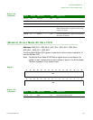
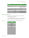
Baud rates This table shows the baud rates achieved with CLK
ref
set to 29.4912:
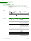
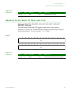
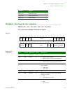
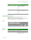
UART Interrupt Enable register
(0x104)
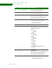
ETBEI 0x1 Enable the Transmitter Holding
Register Empty Interrupt. enables the
Wrapper to write a transmit character
to the UART.
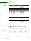
Wrapper Configuration register TX FLOW
Software
1TX Enabled
RXEN 1 Enable Wrapper receive function
TXEN 1 Enable Wrapper transmit function
Control register Field Value Comment
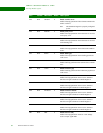
Divisor Baud rate
1 1,843,299
2 921,600
4 460,800
8 230,400
16 115,200
32 57,600
48 38,400
64 28,800
96 19,200
128 14,400
192 9,600
384 4,800
768 2,400


