. . . . .
ANALOG-TO-DIGITAL CONVERTER (ADC) MODULE
ADC control and status registers
www.digiembedded.com 475
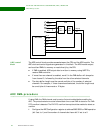
2 Set up the ADC DMA control registers and buffer descriptors (UART channel D).
3 Reset the ADC module by writing a 0 then a 1 to bit 8 in the Module Reset
register at address A090 0180.
4 Flush the ADC DMA FIFO by writing a 1 then a 0 to bit 17 in UART Channel D
Wrapper Configuration register at address 9002 9000.
5 Enable the ADC DMA channel by writing a 1 then a 0 to bit 31 in the UART D DMA
RX Control register at address 9002 8004. 6. Start the ADC by writing a 1 to bit
31 in the ADC Configuration register at address 9003 9000.
. . . . . . . . . . . . . . . . . . . . . . . . . . . . . . . . . . . . . . . . . . . . . . . . . . . . . . . . . . . . . . . . . . . . . . . . . . . . . . . . . .
ADC control and status registers
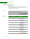
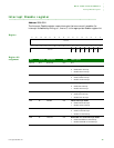
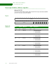
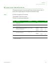
The ADC configuration registers are located at offset 0x9003_9000.
Register address
map
. . . . . . . . . . . . . . . . . . . . . . . . . . . . . . . . . . . . . . . . . . . . . . . . . . . . . . . . . . . . . . . . . . . . . . . . . . . . . . . . . .
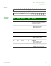
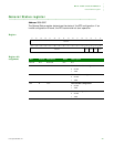
ADC Configuration register
Address: 9003_9000
The ADC Configuration register is the primary Wrapper Configuration register.
Address Description Access Reset value
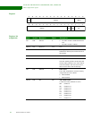
9003_9000 ADC Configuration register R/W 0x00000000
9003_9004 ADC Clock Configuration register R/W 0x00000000
9003_9008 ADC Output 0 register R/W 0x00000000
9003_900C ADC Output 1 register R/W 0x00000000
9003_9010 ADC Output 2 register R/W 0x00000000
9003_9014 ADC Output 3 register R/W 0x00000000
9003_9018 ADC Output 4 register R/W 0x00000000
9003_901C ADC Output 5 register R/W 0x00000000
9003_9020 ADC Output 6 register R/W 0x00000000
9003_9024 ADC Output 7 register R/W 0x00000000


