


. . . . .
I/O HUB MODULE
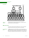
DMA controller
www.digiembedded.com 365
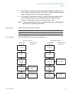
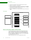
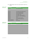
Buffer descriptors The peripheral buffer data is held in buffers in external memory, linked together
using buffer descriptors. The buffer descriptors are 16 bytes in length and are
located contiguously in external memory.
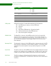
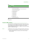
This is the format of the buffer descriptor:
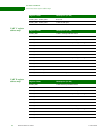
Source address
[pointer]
The source address pointer points to the start of the buffer in system memory.
For transmit channels, the address can start on any byte boundary.
For receive channels, the address must be a 32-bit word aligned.
Buffer length The buffer length is the length of the buffer in bytes, and allows a buffer size of up to
64k–1 bytes to be in a single buffer. Bits 31:16 are not used.
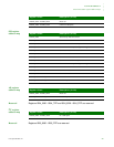
For receive channels, the buffer length field is updated with the actual number of
bytes written to memory, as the peripheral has the ability to close the buffer early.
Control[15] – W The Wrap (W) bit, when set, tells the DMA controller that this is the last buffer
descriptor within the continuous list of descriptors. The next descriptor is found using
the initial DMA channel buffer descriptor pointer. When the W bit is not set, the next
buffer descriptor is found using the 16-byte offset.
Control[14] – I The Interrupt (I) bit, when set, tells the DMA controller to issue an interrupt when the
buffer is closed due to normal channel completion.
Control[13] – L This is the Last (L) bit.
For transmit channels, firmware sets the L bit when the current buffer is the
last in the packet.
For receive channels. hardware sets the L bit when the current buffer is closed
by status bits received from the peripheral device. Status bits can include
conditions such as a character gap timeout, character match, or error
condition.
Control[12] – F This is the Full (F) bit.
Address Description
offset + 0 Source address
offset + 4 Reserved Buffer length
offset + 8 Reserved
offset + C Control Status