. . . . .
SYSTEM CONTROL MODULE
External Interrupt 0–3 Control register
www.digiembedded.com 199
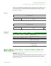
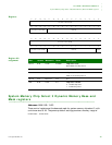
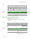
Register
Register bit
assignment
. . . . . . . . . . . . . . . . . . . . . . . . . . . . . . . . . . . . . . . . . . . . . . . . . . . . . . . . . . . . . . . . . . . . . . . . . . . . . . . . . .
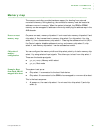
External Interrupt 0–3 Control register
Addresses: A090 0214 / 0218 / 021C / 0220
The External Interrupt Control registers control the behavior of external
interrupts 0–3.
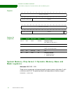
Register
Register bit
assignment
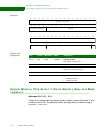
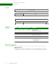
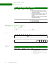
13121110987654321015 14
31 29 28 27 26 25 24 23 22 21 20 19 18 17 1630
Reserved
GENID
Reserved
Bits Access Mnemonic Reset Description
D31:11 N/A Reserved N/A N/A
D10:00 R GENID HW strap
addr[19:09]
General Purpose ID register
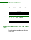
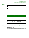
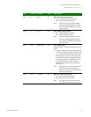
13121110987654321015 14
31 29 28 27 26 25 24 23 22 21 20 19 18 17 1630
Reserved
Reserved
STS CLR PLTY LVEDG
Bits Access Mnemonic Reset Description
D31:04 N/A Reserved N/A N/A
D03 R STS N/A Status
Status of the external signal before edge detect or level
conversion.
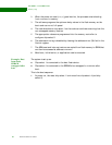
D02 R/W CLR 0x0 Clear
Write a 1, then a 0 to this bit to clear the interrupt
generated by the edge detect circuit.


