


. . . . .
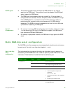
EXTERNAL DMA
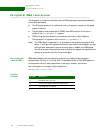
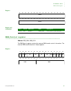
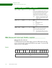
DMA Control register
www.digiembedded.com 349
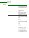
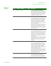
D22:21 R/W DB 0 Destination burst
Defines the AHB maximum burst size allowed
when writing to the destination. Note that the
destination must have enough space, as defined by
this register setting, before asserting REQ.
00 1 unit as set by the destination width field
(D26:25)
01 4 bytes (Recommended for 8-bit devices)
10 16 bytes (Recommended for 16-bit devices)
11 32 bytes (Recommended for 32-bit devices)
D20 R/W SINC_N 0 Source address increment
Controls whether the source address pointers are
incremented after each DMA transfer. The DMA
controller uses these bits in all modes whenever
referring to a memory address.
0 Increment source address pointer
1 Do not increment source address pointer
D19 R/W DINC_N 0 Destination address increment
Controls whether the destination address pointers
are incremented after each DMA transfer. The
DMA controller uses these bits whenever
referring to a memory address.
0 Increment destination address pointer
1 Do not increment destination address pointer
D18 R/W POL 0 Control signal polarity
Defines the active polarity of the dma_req,
dma_done, and PDEN signals.
0 Active high signals
1 Active low signals
D17 R/W MODE 0 Fly-by mode
Defines the direction of data movement for fly-by
DMA transfers.
0 Peripheral-to-memory fly-by-write DMA
transfer
1 Memory-to-peripheral fly-by-read DMA
transfer
Note: This field is not used for DMA transfers
initiated by writing a 1 to the CG field in
this register (D29).
Bit(s) Access Mnemonic Reset Description