


. . . . .
SYSTEM CONTROL MODULE
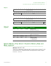
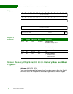
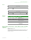
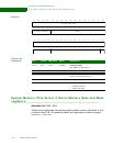
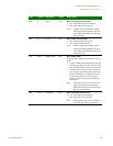
RTC Module Control register
www.digiembedded.com 201
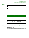
D03 R Rdy int 0x0 RTC clock ready interrupt status
0 RTC clock ready interrupt not asserted
1 RTC clock ready interrupt asserted
Note: The RTC clock ready and RTC module
interrupts are ORed together to the inter-
rupt controller. Read this bit to determine
the actual source.
D02 R Int stat 0x0 RTC module interrupt status
0 RTC module interrupt not asserted
1 RTC module interrupt asserted
Note: The RTC clock ready and RTC module
interrupts are ORed together to the inter-
rupt controller. Read this bit to determine
the actual source.
D01 R/W Standby mode 0x0 RTC standby mode
Allows the RTC module to be placed in low power
mode.
0 The RTC module is placed in standby mode and
cannot be accessed by the CPU. The RTC clock
must be enabled when in standby mode (bit 10).
1 Normal operation. The CPU must wait for the
RTC interrupt and read the status to determine
that the clock change is complete (RTC clock
ready interrupt status bit is set). The clock
change may take up to 30 microseconds after
this bit is set.
Note: This bit must be set to 0 when not access-
ing the RTC registers or battery back
RAM. When early power loss interrupt is
detected, set this bit to 0.
D00 R/W Clk rdy int 0x0 RTC clock ready interrupt clear
0 RTC clock ready interrupt enabled
1 RTC clock ready interrupt cleared
Note: This register must be set, then cleared to
service the RTC clock ready interrupt.
Bits Access Mnemonic Reset Description