. . . . .
I/O CONTROL MODULE
GPIO Configuration registers
www.digiembedded.com 55
. . . . . . . . . . . . . . . . . . . . . . . . . . . . . . . . . . . . . . . . . . . . . . . . . . . . . . . . . . . . . . . . . . . . . . . . . . . . . . . . . .
GPIO Configuration registers
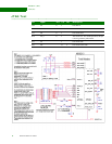
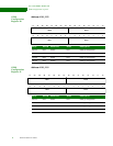
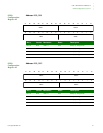
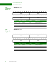
GPIO Configuration registers #0 through #26 contain the configuration information
for each of the 108 GPIO pins. Each GPIO pin can have up to four functions.
Configure each pin for the function and direction needed, using the configuration
options shown below.
GPIO
configuration
options
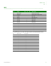
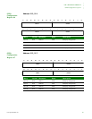
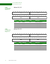
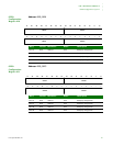
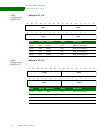
Each GPIO configuration section is set up the same way. This table shows the settings
using bits D07:00; the same settings apply to the corresponding bits in D15:08,
D23:D16, and D31:24.
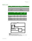
A090_208C Memory Bus Configuration register R/W 007D6344
1 The reset values for all the status bits are undefined because they depend on the state of the GPIO
pins to NS9215.
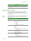
Address Description Access Reset value
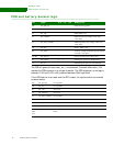
Bit(s) Mnemonic Description
D07:06 Reserved N/A
D05:03 FUNC Use these bits to select the function you want to use. For a definition of each
function, see “General purpose I/O (GPIO)” on page 31.
000 Function #0
001 Function #1
010 Function #2
011 Function #3
100 Function #4 (applicable only for GPIO 0–15)
D02 DIR Controls the pin direction when the FUNC field is configured for GPIO
mode, function #3.
0 Input
1 Output
All GPIO pins reset to the input state.
Note: The pin direction is controlled by the selected function in modes
#0 through #2.
D01 INV Controls the inversion function of the GPIO pin.
0 Disables the inversion function
1 Enables the inversion function
This bit applies to all functional modes.
D00 PUDIS Controls the GPIO pin pullup resistor operation.
0 Enables the pullup
1 Disables the pullup
Note: The pullup cannot be disabled on GPIO[9], GPIO[12], and on
GPIO_A[0] and GPIO_A[1].


