6. System setting
------------------------------------------------------------------------------------------------
----------------------------------------------------------------------------------------
6
- 40
① Type 1 (8bit output)
It outputs after dividing by 2 group. One is the upper 8 bit, The other is the lower
8 bit after the error number transfers the binary code. The signal classifying the
upper data and lower data is the error output selection signal, The strobe signal
deciding the data check timing is the error output STRB signal.
For example
the timing in case of occurring E0101
( 10110 = 006516 = 0000 0000 0110 01012 )
│ ← Lower data → │ ← Upper data→│
+-------------------+
01 -+ 1 +----------0------------------
02 ----------0---------------------0------------------
+-------------------+
03 -+ 1 +----------0------------------
0 0
04 ---------------------------------------------------
05 ----------0---------------------0------------------
+--------1----------+ 0
06 -+ +-----------------------------
+--------1----------+ 0
07 -+ +-----------------------------
0 0
08 ---------------------------------------------------
+-------------------+
The output selection -+ +-----------------------------
+---------+ +---------+
The error selection STRB ------+ +-----------+ +------------
│ ← → │ ← → │ ↔ │ ← → │ ← → │ ← → │
100ms 200ms 50ms 100ms 200ms 100ms
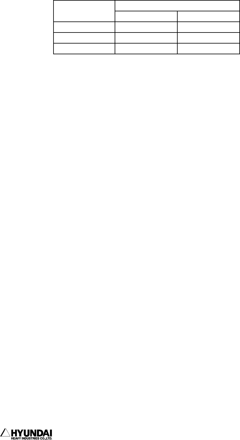
Assignment and Quantity
Signal name
Type 1 Type 2
Error output select Ο : 1EA
×
Error output STRB Ο : 1EA
×
Error output Bit Ο : 8EA Ο : 16EA


