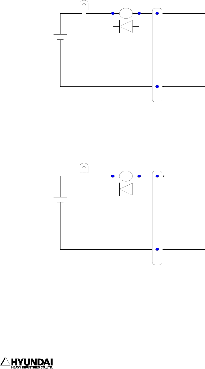
12. Signal connection (3) BD481 circuit
------------------------------------------------------------------------------------------------
----------------------------------------------------------------------------------------
12 - 14
8) INTERLOCK ERROR SIGNAL
It is output this signal in case that interlock signal is not input despite of
exceeding the time set in "SYSTEM [PF5] → 2. CONTROL PARAMETER →
7. Interlock Error Time waiting interlock in playback.
If interlock signal is normally input after this signal is output, the next step
is executed at that state.
9) PROGRAM ACK. SIGNAL
It is output the confirming signal when program is selected by external program
selection. This signal is output for 200msec
24V
output
load
connector
CNOUT2
pin no
(37)
signal
interlock
error
COMOUT7
(39), (40)
24V
output
load
connector
CNOUT2
pin no
(38)
signal
program
ACK
COMOUT7
(39), (40)
(44)
(49), (50)
(User setting)
(User setting)


