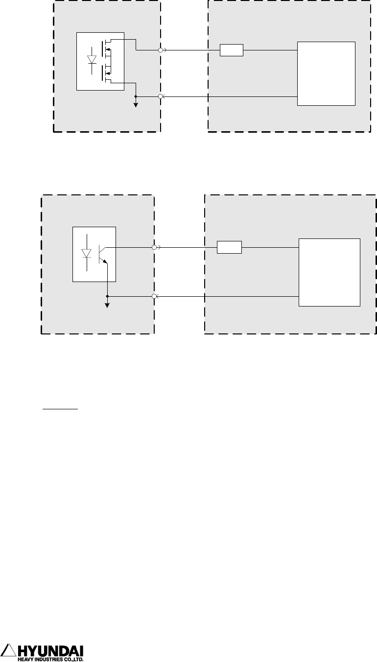
12. Signal connection (3) BD481 circuit
------------------------------------------------------------------------------------------------
----------------------------------------------------------------------------------------
12 - 8
- Connection Diagram
BD431 Board : Common (+) or (-) voltage
COMOUT1,2,3,4,5,6,7,8
BD431 Board
+24V(0V)
0V(+24V)
Output
Signals
User's System
Load
User's SMPS
BD430 Board : Common (-) voltage only
COMOUT1,2,3,4,5,6,7,8
BD430 Board
+24V
0V
Output
Signals
User's System
Load
User's SMPS
Note
(1) Use external power source for power source.
(2) All output signals are from transistor open collector output. So, use them within
the rating. (Otherwise a circuit may be damaged.)
(3) Set noise absorbing diode to a load.


