Hardware Reference Manual 141
Intel
®
IXP2800 Network Processor
Intel XScale
®
Core
3.12.6 Timers
The IXP2800 Network Processor supports four timers. These timers are clocked by the Advanced
Peripheral/Bus Clock (APB-CLK), which runs at 50 MHz to produce the PLPL_APB_CLK,
PLPL_APB_CLK/16, or PLPL_APB_CLK/256 signals. The counters are loaded with an initial
value, count down to 0, and raise an interrupt (if interrupts are not masked).
In addition, timer 4 can be used as a watchdog timer when the watchdog enable bits are configured
to 1. When used as a watchdog timer, and when a count of 0 is encountered, it will initiate the reset
sequence.
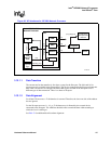
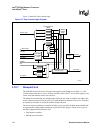
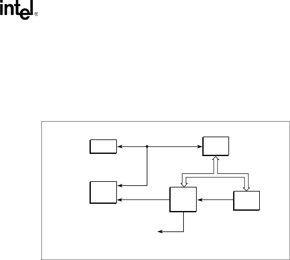
Figure 33 shows the timer control unit interfacing with other functional blocks.
3.12.6.1 Timer Operation
Each timer consists of a 32-bit counter.
By default, the timer counter load register (TCLD) is set to 0xFFFFFFFF. The timer will count
down from 0xFFFFFFFF to 0x00000000, then wrap back to 0xFFFFFFFF and continue to
decrement if the TCLD is not programmed to any value. If a different value is programmed in the
TCLD, then the counter will load this value every time it counts down to 0.
An interrupt is issued to the Intel XScale
®
core whenever the counter reaches 0. The interrupt
signals can be enabled or disabled by the IRQEnable/FIQEnable registers. The interrupt remains
asserted until it is cleared by writing a 1 to the corresponding timer clear register (TCLR).
The counter can be advanced by the clock, clock divided by 16, clock divided by 256, and the
GPIO signals. The clock rate is controlled by the TCTL value programmed into the TCTL
registers. There are four gpio signals, GPIO[3:0] that correspond to Timer 1, 2, 3, and 4,
respectively. These signal are synchronized within the timer-clock domain before driving the
counter.
Figure 33. Timer Control Unit Interfacing Diagram
A9702-04
SHaC
GPIO
gpio[3:0]Timer1,2,3,4
CPP
Watchdog
Reset
Intel
XScale
®
Core
ME
Timers
APB bus
* Intel
®
IXP2800 Network Processor


