280 Hardware Reference Manual
Intel
®
IXP2800 Network Processor
Media and Switch Fabric Interface
8.5.3 TXCDAT/RXCDAT, TXCSOF/RXCSOF, TXCPAR/RXCPAR,
and TXCFC/RXCFC Signals
TXCDAT and RXCDAT, along with TXCSOF/RXCSOF and TXCPAR/RXCPAR are used to send
CSIX Flow Control information from the Egress IXP2800 Network Processor to the Ingress
IXP2800 Network Processor.
The protocol is basically the same as CSIX-LI, but with only four data signals.
TXCSOF is asserted to indicate start of a new CFrame. The format is the same as any normal
CFrame — Base Header, followed by Payload and Vertical Parity; the only difference is that each
CWord is sent on TXCDAT in four cycles, with the most significant bits first. TXCPAR carries odd
parity for each four bits of data. The transmit logic also creates valid Vertical Parity at the end of
the CFrame, with one exception. If the Egress IXP2800 Network Processor detected an error on the
CFrame, it will create bad Vertical parity so that the Ingress IXP2800 Network Processor will
detect that and discard it.
The Egress IXP2800 Network Processor sends CFrames from FCEFIFO in cut-though manner. If
there is no data in FCEFIFO, then the Egress IXP2800 Network Processor alternates sending Idle
CFrames and Dead Cycles. (Note that FCIFIFO never enqueues Idle CFrames in either Full Duplex
or Simplex Modes. The transmitted Idle CFrames are injected by the control state machine, not
taken from the FCEFIFO.)
The Ingress IXP2800 Network Processor asserts RXCFC to indicate that FCIFIFO is full, as
defined by HWM_Control[FCIFIFO_Ext_HWM]. The Egress IXP2800 Network Processor,
upon receiving that signal asserted, will complete the current CFrame, and then transmit Idle
CFrames until RXCFC deasserts. During that time, the Egress IXP2800 Network Processor can
continue to buffer Flow Control CFrames in FCEFIFO; however, if that fills, the further CFrames
mapped to FCEFIFO will be discarded.
Note: If there is no Switch Fabric present, this port could be used for interchip message communication.
FC pins must connect between network processors as in Full Duplex Mode. Set
MSF_RX_CONTROL[DUPLEX_MODE] = 0 and MSF_TX_CONTROL[DUPLEX_MODE]
= 0 (Simplex) and FC_STATUS_OVERRIDE=0x3ff. Microengines write CFrames to the
FCEFIFO CSR as in Simplex Mode. The RXCFC and TXCFC pins must be connected between
network processors to provide flow control.
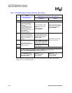
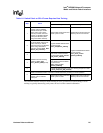
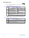
8.6 Deskew and Training
There are three methods of operation that can be used, based on the application requirements.
1. Static Alignment
— the receiver latches all data and control signals at a fixed point in time,
relative to clock.
2. Static Deskew
— the receiver latches each data and control signal at a programmable point in
time, relative to clock. The programming value for each signal is characterized for a given
system design and loaded into deskew control registers at system boot time.
3. Dynamic Deskew
— the transmitter periodically sends a training pattern that the receiver uses
to automatically select the optimal timing point for each data and control signal. The timing
values are loaded into the deskew control registers by the training hardware.


