268 Hardware Reference Manual
Intel
®
IXP2800 Network Processor
Media and Switch Fabric Interface
8.3.3 Transmit Operation Summary
During transmit processing data to be transmitted is placed into the TBUF under Microengine
control, which allocates an element in software. The transmit hardware processes TBUF elements
within a partition, in strict sequential order so the software can track the element to allocate next.
Microengines may write directly into an element by the
msf[write] instruction, or have data
from DRAM written into the element by the
dram[tbuf_wr] instruction. Data can be merged into
the element by doing both.
There is a Transmit Valid bits per element, which marks the element as ready to be transmitted.
Microengines move all data into the element, by either or both of the
msf[write] and
dram[tbuf_wr] instructions to the TBUF. The Microengines also write the element Transmit
Control Word with information about the element. The Microengines should use a single operation
to perform the TCW write, i.e., a single msf[write] with a ref_count of 2. When all of the data
movement is complete, the Microengine sets the element valid bit as shown in the following steps.
1. Move data into TBUF by either or both of
msf[write] and dram[tbuf_wr] instructions to
the TBUF.
2. Wait for 1 to complete.
3. Write Transmit Control Word at TBUF_Element_Control_# address. Using this address sets
the Transmit Valid bit.
Note: When moving data from DRAM to TBUF using
dram[tbuf_wr], it is possible that there could be
an uncorrectable error on the data read from DRAM (if ECC is enabled). In that case, the
Microengine does not get an Event Signal, to prevent use of the corrupt data. The error is recorded
in the DRAM controller (including the number of the Microengine that issued the TBUF_Wr
command — refer to the DRAM chapter for details), and will interrupt the Intel XScale
®
core, if
enabled, so that it can take appropriate action. Such action is beyond the scope of this document.
However, it must include recovering the TBUF element by setting it valid with the Skip bit set in
the Control Word.
The transmit pipeline will be stalled since all TBUF elements must be transmitted in order; it will
be un-stalled when the element is skipped.
8.3.3.1 SPI-4
Transmit control logic sends valid elements on the transmit pins in element order. First, a Control
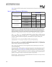
Word is sent — it is formed as shown in Table 100. After the Control Word, the data is sent; the
number of bytes to send is the total of Element Control Word Prepend Length field plus the
Element Control Word Payload Length.
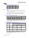
Table 100. Transmit SPI-4 Control Word
SPI-4 Control Word Field Derived from:
Type Type Bit of Element Control Word
EOPS
EOP Bit, Prepend Length, Payload Length of previous element’s Element Control
Word
SOP SOP Bit of Element Control Word
ADR ADR field of Element Control Word
DIP-4 Parity accumulated on previous element’s data and this Control Word


