Hardware Reference Manual 193
Intel
®
IXP2800 Network Processor
DRAM
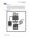
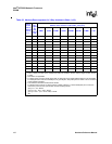
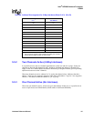
Table 64. Address Rearrangement for 3-Way Interleave (Sheet 2 of 2) (Rev B)
5.5.2 Two Channels Active (2-Way Interleave)
It is possible to have only two channels populated for system cost and area savings. If only two
channels are desired, than channels 0 and 1 should be populated and channel 2 should be left
empty. In the Two Channel Mode, the address interleaving is designed with the goal of spreading
adjacent accesses across the 2 channels.
When two channels are active, address bit 7 is used as the channel select. Addresses that have
address 7 equal to 0 are mapped to channel 0 while those with address 7 equal to 1 are mapped to
channel 1. The address within the channel is {[31:8], [6:0]}.
5.5.3 One Channel Active (No Interleave)
When only one channel is active, all accesses go to that channel. In this case, it is possible for an
access to split across two DRAM banks (which could be in different RDRAMs).
When these bits of address are all
“1”s…
1
Add the value in this CSR to
the address
30:7 K11
28:7 K10
26:7 K9
24:7 K8
22:7 K7
20:7 K6
18:7 K5
16:7 K4
14:7 K3
12:7 K2
10:7 K1
8:7 K0
None Value 0 added.
NOTES:
1. This is a priority encoder; when multiple lines satisfy the condition,
the line with the largest number of ones is used.


