290 Hardware Reference Manual
Intel
®
IXP2800 Network Processor
Media and Switch Fabric Interface
8.8 Interface to Command and Push and Pull Buses
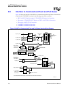
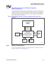
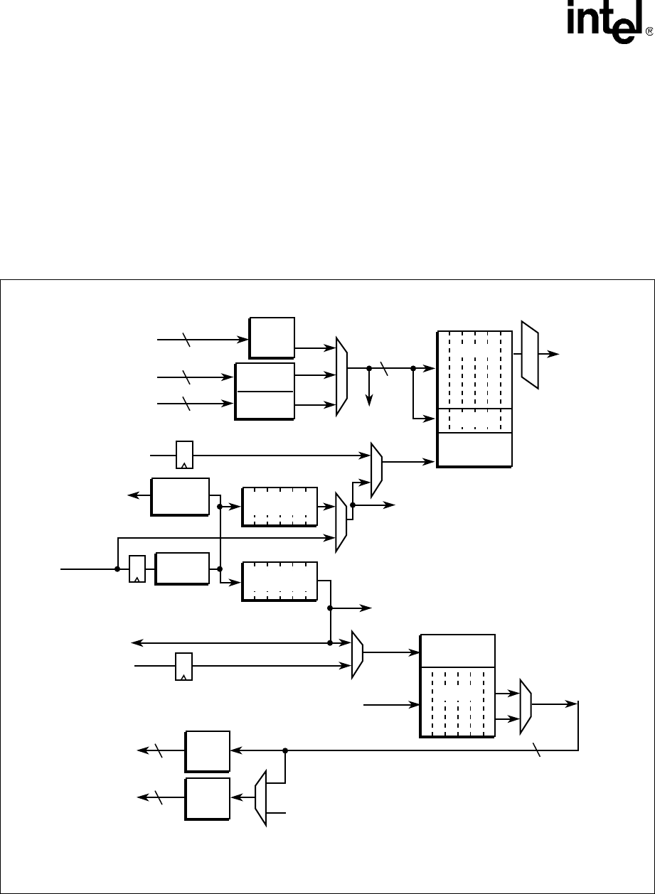
Figure 100 shows the interface of the MSF to the command and push and pull buses. Data transfers
to and from the TBUF/RBUF are done in the following cases (refer to section):
• RBUF or MSF CSR to Microengine S_TRANSFER_IN Register for Instruction:
• Microengine S_TRANSFER_OUT Register to TBUF or MSF CSR for Instruction:
• Microengine to MSF CSR for Instruction:
• From RBUF to DRAM for Instruction:
• From RBUF to DRAM for Instruction:
Figure 100. MSF to Command and Push and Pull Buses Interface Block Diagram
B1630-02
128
D_Push_Bus
MSF CSR Data
TBUF Write
Data
TBUF
Address
RBUF
Address
To MSF
CSRs
DPush
Data
Req
DPull
Data
Req
SPush
Data
Req
To
Transmit
Pins
To MSF CSRs
To MSF CSRs
Byte Align
TBUF
*Data
Write
CMD FIFO
Pull_ID
Buffer
Command
Inlet FIFO
Control*
Address
Decode
RBUF
Address
Decode
SPull Data
FIFO
SPull Data
FIFO
From Receive Pins
Read
Data
Read
CMD FIFO
64
S0_Pull_Bus
U_D_Pull_Bus
64
U_S_Push-ID
(Goes to both
Push Arbiters)
32
32
S1_Pull_Bus
D_Push_ID
CMD B Bus
fast_wr_CMD
ME, Intel
XScale
®
Core Commands
D_Pull_ID
U_S_Pull_ID
(Goes to both
Push Arbiters)
U_S_Push_ID
(Goes to both
Push Arbiters)
32
128
*Data
* The RBUF, TBUF, TBUF Control can be addressed on 32-bit work boundaries.


