210 Hardware Reference Manual
Intel
®
IXP2800 Network Processor
SRAM Interface
Each channel can be expanded in depth according to the number of port enables available. If
external decoding is used, then the number of SRAMs is not limited by the number of port enables
generated by the SRAM controller.
Note: External decoding may require external pipeline registers to account for the decode time,
depending on the desired frequency.
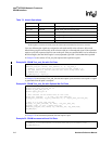
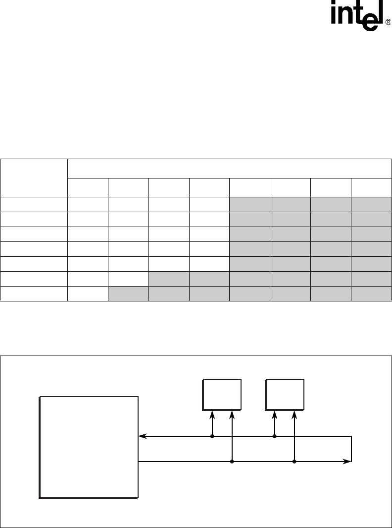
Maximum SRAM system sizes are shown in Table 71. Shaded entries require external decoding,
because they use more port-enables than the SRAM controller can directly supply.
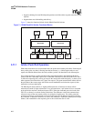
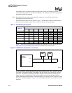
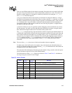
Figure 75 shows how the SRAM clocks on a channel are connected. For receiving data from the
SRAMs, the clock path and data path are matched to meet hold time requirements.
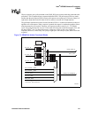
It is also possible to pipeline the SRAM signals with external registers. This is useful for the case
when there is considerable loading on the address and data signals, which would slow down the
cycle time. The pipeline stages make it possible to keep the cycle time fast by fanning out the
address, byte write, and data signals. The RAM read data may also be put through a pipeline
register, depending on configuration. External decoding of port selects can also be done to expand
the number of SRAMs supported. Figure 76 is a block diagram that shows the concept of external
pipelining.
Table 71. Total Memory per Channel
SRAM Size
Number of SRAMs on Channel
12345678
512K x 18 1 MB 2 MB 3 MB
4 MB 5 MB 6 MB 7 MB 8 MB
1M x 18 2 MB 4 MB 6 MB 8 MB
10 MB 12 MB 14 MB 16 MB
2M x 18 4 MB 8 MB 12 MB 16 MB 20 MB 24 MB 28 MB 32 MB
4M x 18 8 MB 16 MB 24 MB 32 MB 64 MB NA NA NA
8M x 18 16 MB 32 MB 48 MB 64 MB NA NA NA NA
16M x 18 32 MB 64 MB NA NA NA NA NA NA
32M x 18 64 MB NA NA NA NA NA NA NA
Figure 75. SRAM Clock Connection on a Channel
A9734-02
C, C_n
K, K_n
SRAM SRAM
Intel
®
IXP2800
Network
Processor


