


368 Hardware Reference Manual
Intel
®
IXP2800 Network Processor
Clocks and Reset
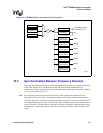
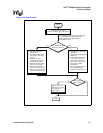
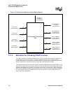
Once in operation, if the watchdog timer expires with watchdog timer enable bit WDE from Timer
Watchdog Enable register set, a reset pulse from the watchdog timer logic goes to PLL unit after
passing through a counter to guarantee minimum assertion time, which in turn resets the
IXP_RESETn registers that cause the entire chip to be reset.
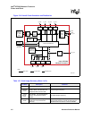
Figure 134 explains the reset generation for the PLL logic and for the rest of the core. CORE_RST
is used inside the IXP2800 to reset everything; PLL_RST can be disabled.
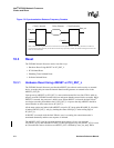
10.3.5 Reset Removal Operation Based on CFG_PROM_BOOT
Reset removal based on the CFG_PROM_BOOT strap option (BOOT_PROM) can be divided into
two parts:
1. When CFG_PROM_BOOT is 1 (BOOT_PROM is present).
2. When CFG_PROM_BOOT is 0 (BOOT_PROM is not present).
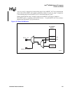
10.3.5.1 When CFG_PROM_BOOT is 1 (BOOT_PROM is Present)
After CORE_RST is de-asserted, reset from the Intel XScale
®
core, SHaC, and CMDARB is
removed. Once the Intel XScale
®
core reset is removed, the Intel XScale
®
core starts initializing
the chip. The Intel XScale
®
core writes the ‘clock control CSR’ to define the operating frequencies
of different units. The Intel XScale
®
core writes IXP_RESET0[21] to allow the PCI logic to start
accepting transactions on the PCI bus as part of initialization process.
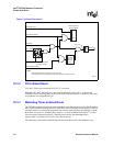
10.3.5.2 When CFG_PROM_BOOT is 0 (BOOT_PROM is Not Present)
After CORE_RST is de-asserted, IXP_RESET0[21] is set, allowing the PCI unit to start accepting
transactions on the PCI bus. In this mode, the Intel XScale
®
core is kept in reset. Reset from
DRAM logic is removed by the PCI host by writing 0 to specific bits in the IXP_RESET0 register.
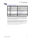
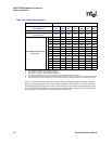
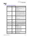
10.3.6 Strap Pins
The IXP2800 Strap pins for reset and initialization operation are described in Table 149.