364 Hardware Reference Manual
Intel
®
IXP2800 Network Processor
Clocks and Reset
10.3 Reset
The IXP2800 Network Processor can be reset four ways.
• Hardware Reset Using nRESET or PCI_RST_L.
• PCI-Initiated Reset.
• Watchdog Timer Initiated Reset.
• Software Initiated Reset.
10.3.1 Hardware Reset Using nRESET or PCI_RST_L
The IXP2800 Network Processor provides the nRESET pin so that it can be reset by an external
device. Asserting this pin resets the internal functions and generates an external reset via the
nRESET_OUT pin.
Upon power-up, nRESET (or PCI_RST_L) must remain asserted for 1ms after VDD is stable to
properly reset the IXP2800 Network Processor and ensure that the external clocks are stable. While
nRESET is asserted, the processor is held in reset. When nRESET is released, the Intel XScale
®
core begins executing from address 0x0. If PCI_RST_L is input to the chip, nRESET should be
removed before or at the same time as PCI_RST_L.
All the strap options are latched with nRESET except for PCI strap option BOARD_IS_64 which
is latched with PCI_RST_L only (by latching the status of REQ64_L at the trailing edge of
PCI_RST_L).
If nRESET is asserted, while the Intel XScale
®
core is executing, the current instruction is
terminated abnormally and the reset sequence is initiated.
The nRESET_OUT signal de-assertion depends upon settings of reset_out_strap and
IXP_RESET_0[22] also called the EXTRST_EN bit. During power up, IXP_RESET_0[22] is reset
to 0; therefore the value to be driven on nRESET_OUT is defined by reset_out_strap. When
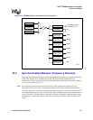
Figure 132. Synchronization Between Frequency Domains
Clock A domain
Data_out
Clock B
Delay Element
Clock A and Clock B are guaranteed to be at least two PLL clocks apart; therefore, if the delay element is such that it is
more than the hold time required by clock B but less than the setup required by Clock B, data should transfer glitch-free from the
Clock A to Clock B domain.
Data_in
Clock A
Clock B domain


