Hardware Reference Manual 359
Intel
®
IXP2800 Network Processor
Clocks and Reset
Clocks and Reset 10
This section describes the IXP2800 Network Processor clocks and reset. Refer to the Intel
®
IXP2800 Network Processor Hardware Initialization Reference Manual for information about the
initialization of all units of the IXP2800 Network Processor.
10.1 Clocks
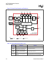
The block diagram in Figure 130 shows how the IXP2800 Network Processor implements an
onboard clock generator to generate the internal clocks used by the various functional units in the
device. It takes an external reference frequency and multiplies it to a higher frequency clock using
a PLL. That clock is then divided down by a set of programmable dividers to provide clocks to
SRAM and DRAM controllers.
The Intel XScale
®
core and Microengines get clocks using fixed divide ratios. The Media and
Switch Fabric Interface clock is selected based on the strap pin (CFG_MSF_FREQ_SEL) so that
when CFG_MSF_FREQ_SEL is high, an internally-generated clock using the programmable
divider is used and when CFG_MSF_FREQ_SEL is low, an externally-received clock on the MSF
interface is used.
The PCI controller uses external clocks. Each of the units also interfaces to internal buses, which
run at ½ the Microengine frequency. Figure 130 shows the overall clock generation and
distribution and Table 147 summarizes the clock usage.


