Hardware Reference Manual 85
Intel
®
IXP2800 Network Processor
Intel XScale
®
Core
3.3.3 Interaction of the MMU, Instruction Cache, and Data Cache
The MMU, instruction cache, and data/mini-data cache may be enabled/disabled independently.
The instruction cache can be enabled with the MMU enabled or disabled. However, the data cache
can only be enabled when the MMU is enabled. Therefore only three of the four combinations of
the MMU and data/mini-data cache enables are valid (see Table 23). The invalid combination will
cause undefined results.
3.3.4 Control
3.3.4.1 Invalidate (Flush) Operation
The entire instruction and data TLB can be invalidated at the same time with one command or they
can be invalidated separately. An individual entry in the data or instruction TLB can also be
invalidated.
Globally invalidating a TLB will not affect locked TLB entries. However, the invalidate-entry
operations can invalidate individual locked entries. In this case, the locked remains in the TLB, but
will never “hit” on an address translation. Effectively, a hole is in the TLB. This situation may be
rectified by unlocking the TLB.
3.3.4.2 Enabling/Disabling
The MMU is enabled by setting bit 0 in coprocessor 15, register 1 (Control register). When the
MMU is disabled, accesses to the instruction cache default to cacheable and all accesses to data
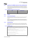
memory are made non-cacheable. A recommended code sequence for enabling the MMU is shown
in Example 14.
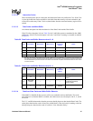
Table 23. Valid MMU and Data/Mini-Data Cache Combinations
MMU Data/Mini-data Cache
Off Off
On Off
On On
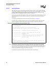
Example 14. Enabling the MMU
; This routine provides software with a predictable way of enabling the MMU.
; After the CPWAIT, the MMU is guaranteed to be enabled. Be aware
; that the MMU will be enabled sometime after MCR and before the instruction
; that executes after the CPWAIT.
; Programming Note: This code sequence requires a one-to-one virtual to
; physical address mapping on this code since
; the MMU may be enabled part way through. This would allow the instructions
; after MCR to execute properly regardless the state of the MMU.
MRC P15,0,R0,C1,C0,0; Read CP15, register 1
ORR R0, R0, #0x1; Turn on the MMU
MCR P15,0,R0,C1,C0,0; Write to CP15, register 1
; The MMU is guaranteed to be enabled at this point; the next instruction or
; data address will be translated.


