262 Hardware Reference Manual
Intel
®
IXP2800 Network Processor
Media and Switch Fabric Interface
8.3 Transmit
The transmit section consists of:
• Transmit Pins (Section 8.3.1)
• Transmit Buffer (Section 8.3.2)
• Byte Aligner (Section 8.3.2)
Each of these is described below.
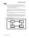
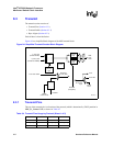
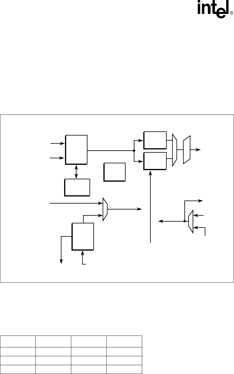
Figure 94 is a simplified block diagram of the MSF transmit block.
8.3.1 Transmit Pins
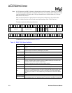
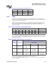
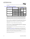
The use of the transmit pins is a function of the protocol (which is determined by TBUF partition in
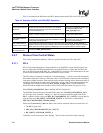
MSF_Tx_Control CSR) as shown in Table 94.
Figure 94. Simplified Transmit Section Block Diagram
A9343-01
RXCDAT
From Other CSRs
Internal Clock
for Transmit
Logic
S_Pull_Data
(32-bits from ME)
D_Push_Data
(64-bits from DRAM)
TCLK
TCLK REF
RXCFC
(FCIFIFO full)
RXCSRB
(Ready Bits)
Internal
Clock
ME Reads
(S_Push_Bus)
Valid
Element
Logic
TDAT
TCTL
TPAR
FCIFIFO
- - - - - -
- - - - - -
- - - - - -
- - - - - -
TBUF
- - - - - -
- - - - - -
- - - - - -
- - - - - -
CSIX
Protocol
Logic
SPI-4
Protocol
Logic
Control
Byte Align
Table 94. Transmit Pins Usage by Protocol (Sheet 1 of 2)
Name Direction SPI-4 Use CSIX Use
TCLK Output TDCLK RxClk
TDAT[15:0] Output TDAT[15:0] RxData[15:0]
TCTL Output TCTL RxSOF


