


Example Configuration
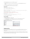
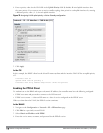
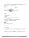
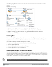
In the following example, the controller operates within an enterprise network. VLAN 1 is the outside VLAN. Traffic
from VLAN 6 is source NATed using the IP address of the controller. In this example, the IP address assigned to
VLAN 1 is used as the controller’s IP address; thus traffic from VLAN 6 would be source NATed to 66.1.131.5.
Figure 34: Example: Source NAT using Controller IP Address
In the WebUI
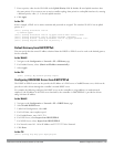
1. Navigate to the Configuration > Network > VLANs page. Click Add to configure VLAN 6 (VLAN 1 is
configured through the Initial Setup).
a. Enter 6 for the VLAN ID.
b. Click Apply.
2. Navigate to the Configuration > Network > IP > IP Interfaces page.
3. Click Edit for VLAN 6:
a. Select Use the following IP address.
b. Enter 192.168.2.1 for the IP Address and 255.255.255.0 for the Net Mask.
c. Select the Enable source NAT for this VLAN checkbox.
4. Click Apply.
In the CLI
(host) (config) #interface vlan 1
ip address 66.1.131.5 255.255.255.0
(host) (config) #interface vlan 6
(host) (config) #ip address 192.168.2.1 255.255.255.0
ip nat inside
ip default-gateway 66.1.131.1
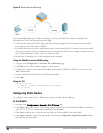
Inter-VLAN Routing
On the controller, you can map a VLAN to a layer-3 subnetwork by assigning a static IP address and netmask or by
configuring a DHCP or PPPoE server to provide a dynamic IP address and netmask to the VLAN interface. The
controller, acting as a layer-3 switch, routes traffic between VLANs that are mapped to IP subnetworks; this
forwarding is enabled by default.
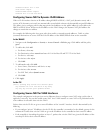
In Figure 35, VLAN 200 and VLAN 300 are assigned the IP addresses 2.1.1.1/24 and 3.1.1.1/24, respectively. Client
A in VLAN 200 is able to access server B in VLAN 300 and vice versa, provided that there is no firewall rule
configured on the controller to prevent the flow of traffic between the VLANs.
DellPowerConnectW-SeriesArubaOS6.2 | User Guide NetworkConfigurationParameters | 122