


761 | ExternalServicesInterface DellPowerConnectW-SeriesArubaOS6.2 | User Guide
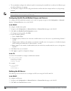
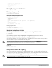
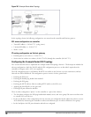
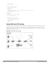
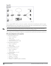
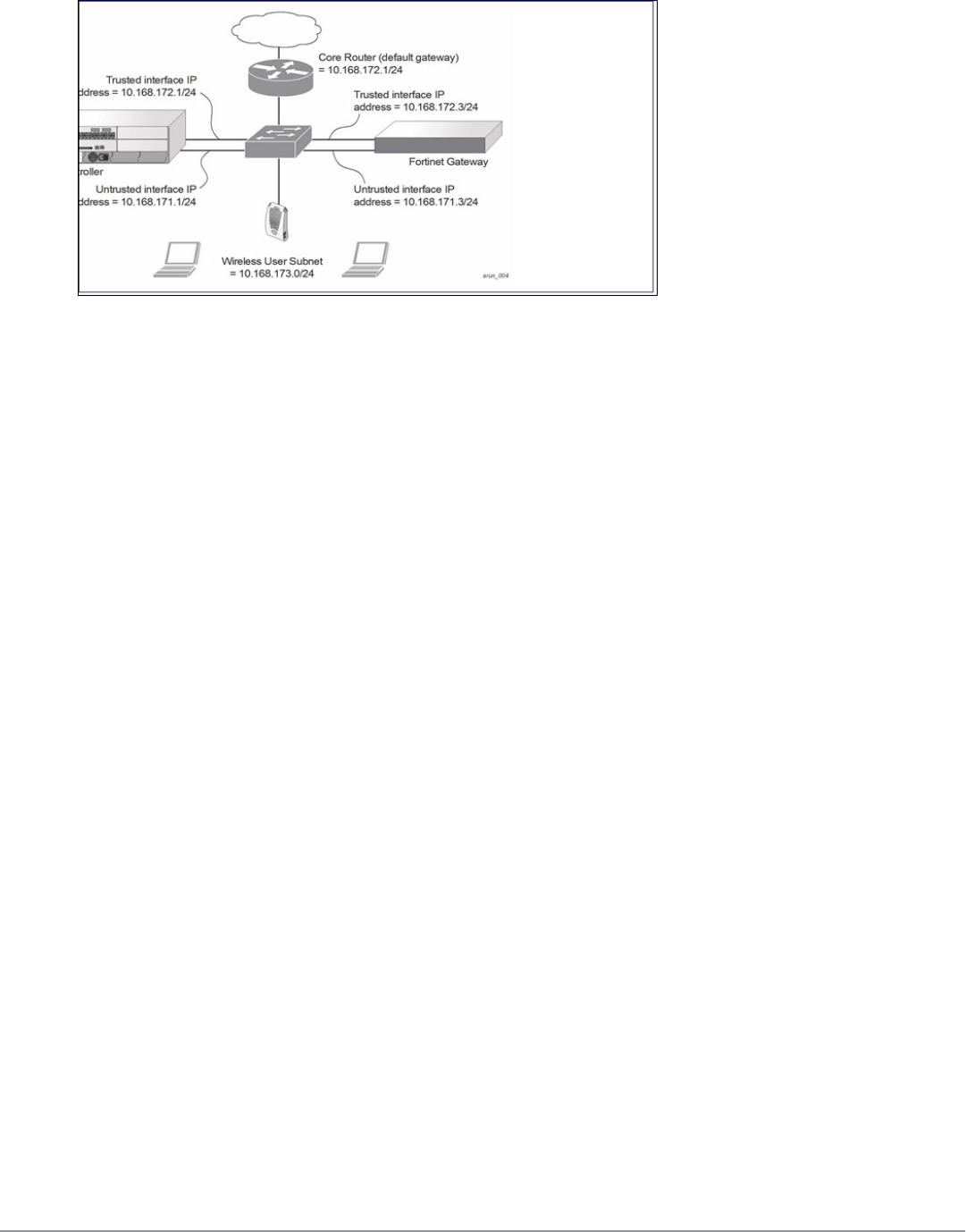
Figure 347: Example Route-Mode Topology
In the topology shown, the following configurations are entered on the controller and Fortinet gateway:
ESI server configuration on controller
l Trusted IP address = 10.168.172.3 (syslog source)
l Untrusted IP address = 10.168.171.3
l Mode = route
IP routing configuration on Fortinet gateway
l Default gateway (core router) = 10.168.172.1
l Static route for wireless user subnet (10.168.173.0/24) through the controller (10.168.171.2)
Configuring the Example Routed ESI Topology
This section describes how to implement the example routed ESI topology shown in . The description includes the
relevant configuration—both the WebUI and the CLI configuration processes are described—required on the
controller to integrate with a AVF server appliance.
The ESI configuration process will redirect all HTTP user traffic to the Fortinet server for examination, and any
infected user will be blacklisted. The configuration process consists of these general tasks:
l Defining the ESI server.
l Defining the default ping health check method.
l Defining the ESI group.
l Defining the HTTP redirect filter for sending HTTP traffic to the ESI server.
l Applying the firewall policy to the guest role.
l Defining ESI parser domains and rules.
There are three configuration “phases” on the controller as a part of the solution.
l The first phase configures the ESI
ping health-check method
,
servers
, and
server groups
.The term
server
here refers
to external AVF server devices.
l In the second phase of the configuration task, the user roles are configured with the redirection policies (session
ACL definition) instructing the controller to redirect the different types of traffic to different server groups.
l In the final phase, the ESI parser domains and rules are configured.