


DellPowerConnectW-SeriesArubaOS6.2 | User Guide OSPFv2 | 152
Chapter 10
OSPFv2
OSPFv2 (Open Shortest Path First) is a dynamic Interior Gateway routing Protocol (IGP) based on IETF RFC
2328. The premise of OSPF is that the shortest or fastest routing path is used. Dell’s implementation of OSPFv2
allows Dell controllers to deploy effectively in a Layer 3 topology. Dell controllers can act as default gateway for all
clients and forward user packets to the upstream router. The information in this chapter is in the following sections:
l "Understanding OSPF Deployment Best Practices and Exceptions" on page 152
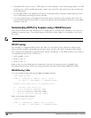
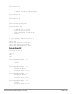
l "Understanding OSPFv2 by Example using a WLAN Scenario" on page 153
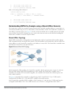
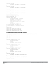
l "Understanding OSPFv2 by Example using a Branch Office Scenario" on page 154
l "Configuring OSPF " on page 155
l "Sample Topology and Configuration" on page 157
Understanding OSPF Deployment Best Practices and Exceptions
OSPF is a robust routing protocol addressing various link types and deployment scenarios, the Dell implementation
applies to two main use cases; WLAN Scenario and Branch Office Scenario.
l OSPF is disabled by default.
l Dell controllers support only one OSPF instance.
l Maximum OSPF routes is 1K.
l Convergence takes between 5 and 15 seconds.
l All area types are supported.
l Multiple configured areas are supported.
l A Dell controller can act as ABR (Area border router).
l OSPF supports VLAN and GRE tunnel interfaces.
l To run OSPF over IPSec tunnels, a Layer 3 GRE tunnel is configured between two routers with GRE destination
addresses as the inner address of the IPsec tunnel. OSPF is enabled on the Layer 3 GRE tunnel interface and all
of the OSPF control packets undergo GRE encapsulation before entering the IPsec tunnels.
The default MTU value for a Layer 3 GRE tunnel in a Dell controller is 1100. When running OSPF over a GRE
tunnel between a Dell controller and another vendor’s router, the MTU values must be the same on both sides
of the GRE tunnel.
Below are some guidelines regarding deployment and topology for this release of OSPFv2.
l In WLAN scenario, configure the Dell controller and all upstream routers in totally stub area; in Branch Office
scenario, configure as stub area so that the Branch Office controller can receive corporate subnets.
l In the WLAN scenario upstream router, only configure the interface connected to the controller in the same area
as the controller. This will minimize the number of local subnet addresses advertised by the upstream router to
the controller.
l Use the upstream router as the designated router (DR) for the link/interface between the controller and the
upstream router.