


User’s Manual
Preliminary PPC440x5 CPU Core
mmu.fm.
September 12, 2002
Page 147 of 589
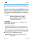
which means that the bytes are arranged with the most-significant byte at the lowest-numbered memory
address. The operands in a memory page with E=1 are arranged with little-endian byte ordering, which
means that the bytes are arranged with the least-significant byte at the lowest-numbered address.
See Byte Ordering on page 42 for a more detailed explanation of big-endian and little-endian byte ordering.
5.6.6 User-Definable (U0–U3)
The PPC440x5 core provides four user-definable (U0–U3) storage attributes which can be used to control
system-dependent behavior of the storage system. By default, these storage attributes do not have any effect
on the operation of the PPC440x5 core, although all storage accesses indicate to the memory subsystem the
values of U0–U3 using the corresponding transfer attribute interface signals. The specific system design may
then take advantage of these attributes to control some system-level behaviors. As an example, one of the
user-definable storage attributes could be used to enable code compession using the IBM CodePack core, if
this function is included within a specific implementation incorporating the PPC440x5 core.
On the other hand, the PPC440x5 core can be programmed to make specific use of two of the four user-
definable storage attributes. Specifically, by enabling the function using a control bit in the MMUCR (see
Memory Management Unit Control Register (MMUCR) on page 148), the U1 storage attribute can be used to
designate whether storage accesses to the associated memory page should use the “normal” or “transient”
region of the respective cache. Similarly, another control bit in the MMUCR can be set to enable the U2
storage attribute to be used to control whether or not store accesses to the associated memory page which
miss in the data cache should allocate the line in the cache. The U1 or U2 storage attributes do not affect
PPC440x5 core operation unless they are enabled using the MMUCR to perform these specific functions.
See Instruction and Data Caches on page 95 for more information on the mechanisms that can be controlled
by the U1 and U2 storage attributes.
The U0 and U3 storage attributes have no such mechanism that enables them to control any specific function
within the PPC440x5 core.
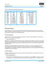
5.6.7 Supported Storage Attribute Combinations
Storage modes where both W = 1 and I = 1 (which would represent write-through but caching inhibited
storage) are not supported. For all supported combinations of the W and I storage attributes, the G, E, and
U0-U3 storage attributes may used in any combination.
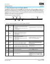
5.7 Storage Control Registers
In addition to the two registers described below, the MSR[IS,DS] bits specify which of the two address spaces
the respective instruction or data storage accesses are directed towards. Also, the MSR[PR] bit is used by
the access control mechanism. See Machine State Register (MSR) on page 165 for more detailed informa-
tion on the MSR and the function of each of its bits.