


User’s Manual
Preliminary PPC440x5 CPU Core
overview.fm.
September 12, 2002
Page 29 of 589
– Decrementer with auto-reload capability
– Fixed Interval Timer (FIT)
– Watchdog Timer with critical interrupt and/or auto-reset
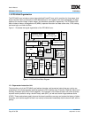
• Multiple core Interfaces defined by the IBM CoreConnect on-chip system architecture
• PLB interfaces
• Three independent 128-bit interfaces for instruction reads, data reads, and data writes
• Glueless attachment to 32-, 64-, or 128-bit CoreConnect system environments
• Multiple CPU:PLB frequency ratios supported (N:1, N:2, N:3)
• 6.4 GB/sec maximum data rate to CPU
• On-chip memory (OCM) integration capability over the PLB interface
• Auxiliary Processor Unit (APU) Port
• Provides functional extensions to the processor pipelines, including GPR file operations
• 128-bit load/store interface (direct access between APU and the primary data cache)
• Interface can support APU execution of all PowerPC floating point instructions
• Attachment capability for DSP co-processing such as accumulators and SIMD computation
• Enables customer-specific instruction enhancements for multimedia applications
• Device Control Register (DCR) interface for independent access to on-chip control registers
• Avoids contention for high-bandwidth PLB system bus
• Clock and power management interface
• JTAG debug interface
1.2 The PPC440x5 as a PowerPC Implementation
The PPC440x5 core implements the full, 32-bit fixed-point subset of the Book-E Enhanced PowerPC Archi-
tecture. The PPC440x5 core fully complies with these architectural specifications. The 64-bit operations of
the architecture are not supported, and the core does not implement the floating point operations, although a
floating point unit (FPU) may be attached (using the APU interface). Within the core, the 64-bit operations and
the floating point operations are trapped, and the floating point operations can be emulated using software.
See Appendix A of the Book-E Enhanced PowerPC Architecture specification for more information on 32-bit
subset implementations of the architecture.
Note: This document differs from the Book-E architecture specification in the use of bit numbering for
architected registers. Specifically, Book-E defines the full, 64-bit instruction set architecture, and
thus all registers are shown as having bit numbers from 0 to 63, with bit 63 being the least
significant. On the other hand, this document describes the PPC440x5 core, which is a 32-bit
subset implementation of the architecture. Accordingly, all architected registers are described as
being 32 bits in length, with the bits numbered from 0 to 31, and with bit 31 being the least
significant. Therefore, when this document makes reference to register bit numbers from 0 to 31,
they actually correspond to bits 32 to 63 of the same register in the Book-E architecture
specification.