


User’s Manual
Preliminary PPC440x5 CPU Core
timers.fm.
September 12, 2002
Page 213 of 589
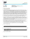
When a Fixed Interval Timer exception occurs, the exception status is recorded by setting the Fixed interval
Timer Interrupt Status (FIS) field of the TSR to 1. A Fixed Interval Timer interrupt will occur if it is enabled by
both the Fixed Interval Timer Interrupt Enable (FIE) field of the TCR and by MSR[EE]. Fixed-Interval Timer
Interrupt on page 192 provides more information on the handling of Fixed Interval Timer interrupts.
The Fixed Interval Timer interrupt handler software should clear TSR[FIS] before re-enabling MSR[EE], in
order to avoid another Fixed Interval Timer interrupt due to the same exception (unless TCR[FIE] is cleared
instead).
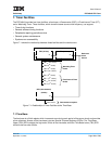
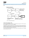
7.4 Watchdog Timer
The Watchdog Timer provides a mechanism for system error recovery in the event that the program running
on the PPC440x5 core has stalled and cannot be interrupted by the normal interrupt mechanism. The
Watchdog Timer can be configured to cause a critical-class Watchdog Timer interrupt upon the expiration of
a single period of the Watchdog Timer. It can also be configured to invoke a processor-initiated reset upon
the expiration of a second period of the Watchdog Timer.
A Watchdog Timer exception occurs on a 0→1 transition of a selected bit from the time base. Note that a
Watchdog Timer exception will also occur if the selected time base bit transitions from 0→1 due to a mtspr
instruction
that writes 1 to that time base bit when its previous value was 0.
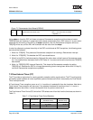
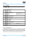
The Watchdog Timer Period (WP) field of the TCR selects one of four bits from the time base, as shown in
Table 7-2.
The action taken upon a Watchdog Timer exception depends upon the status of the Enable Next Watchdog
(ENW) and Watchdog Timer Interrupt Status (WIS) fields of the TSR at the time of the exception. When
TSR[ENW] = 0, the next Watchdog Timer exception is “disabled”, and the only action to be taken upon the
exception is to set TSR[ENW] to 1. By clearing TSR[ENW], software can guarantee that the time until the
next enabled Watchdog Timer exception will be at least one full Watchdog Timer period (and a maximum of
two full Watchdog Timer periods).
When TSR[ENW] = 1, the next Watchdog Timer exception is enabled, and the action to be taken upon the
exception depends on the value of TSR[WIS] at the time of the exception. If TSR[WIS] = 0, then the action is
to set TSR[WIS] to 1, at which time a Watchdog Timer interrupt will occur if enabled by both the Watchdog
Timer Interrupt Enable (WIE) field of the TCR and by the Critical Interrupt Enable (CE) field of the MSR. The
Watchdog Timer interrupt handler software should clear TSR[WIS] before re-enabling MSR[CE], in order to
0b11 TBL
7
2
25
clocks 83.9 ms
Table 7-2. Watchdog Timer Period Selection
TCR[WP] Time Base Bit
Period
(Time Base Clocks)
Period
(400 MHz Clock)
0b00 TBL
11
2
21
clocks 5.2 ms
0b01 TBL
7
2
25
clocks 83.9 ms
0b10 TBL
3
2
29
clocks 1.34 s
0b11 TBU
31
2
33
clocks 21.47 s
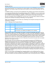
Table 7-1. Fixed Interval Timer Period Selection (continued)
TCR[FP] Time Base Bit
Period
(Time Base Clocks)
Period
(400 Mhz Clock)