


User’s Manual
PPC440x5 CPU Core Preliminary
Page 96 of 589
cache.fm.
September 12, 2002
ated with the line that currently resides in that way. The middle-order address bits form an index to select a
specific set of the cache, while the five lowest-order address bits form a byte-offset to choose a specific byte
(or bytes, depending on the size of the operation) from the 32-byte cache line.
4.1.1 Cache Line Replacement Policy
Memory addresses are specified as being cacheable or caching inhibited on a page basis, using the caching
inhibited (I) storage attribute (see Caching Inhibited (I) on page 145). When a program references a cache-
able memory location and that location is not already in the cache (a cache miss), the line may be brought
into the cache (a cache line fill operation) and placed into any one of the ways within the set selected by the
middle portion of the address (the specific address bits that select the set are specified in Table 4-2). If the
particular way within the set already contains a valid line from some other address, the existing line is
removed and replaced by the newly referenced line from memory. The line being replaced is referred to as
the victim.
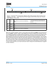
The way selected to be the victim for replacement is controlled by a field within a Special Purpose Register
(SPR). There is a separate “victim index field” for each set within the cache. The registers controlling the
victim selection are shown in Figure 4-1.
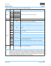
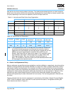
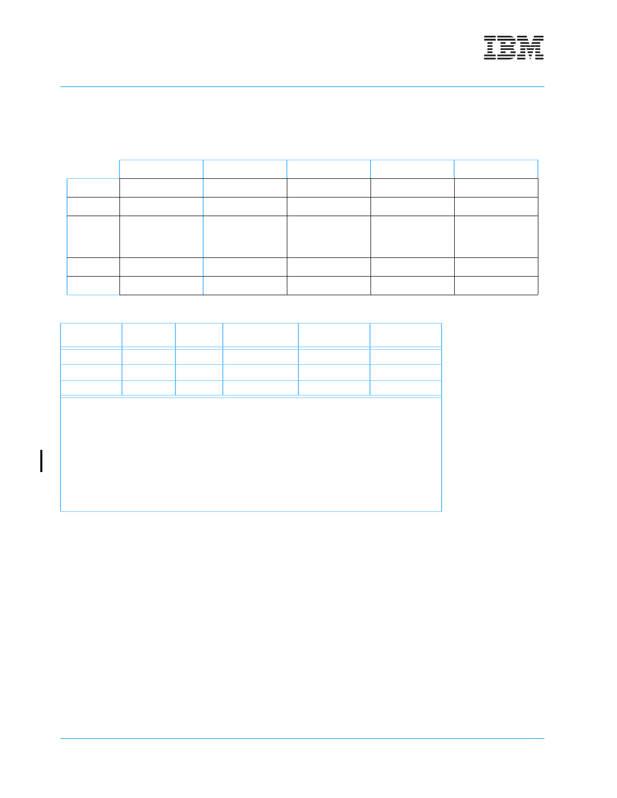
Table 4-1. Instruction and Data Cache Array Organization
Way 0 Way 1
• • •
Way w –2 Wayw –1
Set 0 Line 0 Line n
• • •
Line (w –2)n Line (w –1)n
Set 1 Line 1 Line n +1
• • •
Line (w –2)n + 1 Line (w –1)n +1
•
•
•
•
•
•
•
•
•
•
•
•
•
•
•
•
•
•
Set n – 2 Line n – 2 Line 2n –2
• • •
Line (w –1)n – 2 Line wn –2
Set
n – 1 Line n – 1 Line 2n –1
• • •
Line (w –1)n – 1 Line wn –1
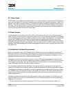
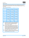
Table 4-2. Cache Sizes and Parameters
Array Size w (Ways) n (Sets)
Tag
Address Bits
1
Set
Address Bits
Byte Offset
Address Bits
8KB 32 8 A
0:23
A
24:26
A
27:31
16KB 64 8 A
0:23
A
24:26
A
27:31
32KB 64 16 A
0:22
A
23:26
A
27:31
Note 1: The tag address bits shown in the table refer to the effective address bits,
and are for illustrative purposes only. Because the instruction cache is
tagged with the virtual address, and the data cache is tagged with the real
address, the actual tag address bits contained within each array are
different. See Figure 4-8 and Figure 4-9 on page 113 for instruction cache
tag information, and Figure 4-10 and Figure 4-11 on page 128 for data
cache tag information. Also, see “Instruction Cache Synonyms” on
page -107 for details on instruction cache synonyms associated with the use
of virtual tags for the instruction cache.