


User’s Manual
Preliminary PPC440x5 CPU Core
intrupts.fm.
September 12, 2002
Page 163 of 589
Interrupt processing consists of saving a small part of the processor state in certain registers, identifying the
cause of the interrupt in another register, and continuing execution at the corresponding interrupt vector loca-
tion. When an exception exists and the corresponding interrupt type is enabled, the following actions are
performed, in order:
1. SRR0 (for non-critical class interrupts) or CSRR0 (for critical class interrupts) or MCSRR0 (for Machine
Check interrupts) is loaded with an instruction address that depends on the type of interrupt; see the spe-
cific interrupt description for details.
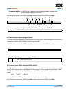
2. The ESR is loaded with information specific to the exception type. Note that many interrupt types can only
be caused by a single type of exception, and thus do not need nor use an ESR setting to indicate the
cause of the interrupt. Machine Check interrupts load the MCSR
3. SRR1 (for non-critical class interrupts) or CSRR1 (for critical class interrupts) or MCSRR1 (for Machine
Check interrupts) is loaded with a copy of the contents of the MSR.
4. The MSR is updated as described below. The new values take effect beginning with the first instruction
following the interrupt.
• MSR[WE,EE,PR,FP,FE0,DWE,FE1,IS,DS] are set to 0 by all interrupts.
• MSR[CE,DE] are set to 0 by all critical class interrupts and left unchanged by all non-critical class
interrupts.
• MSR[ME] is set to 0 by Machine Check interrupts and left unchanged by all other interrupts.
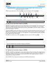
See Machine State Register (MSR) on page 165 for more detail on the definition of the MSR.
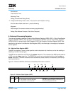
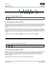
5. Instruction fetching and execution resumes, using the new MSR value, at the interrupt vector address,
which is specific to the interrupt type, and is determined as follows:
IVPR
0:15
|| IVORn
16:27
|| 0b0000
where n specifies the IVOR register to be used for a particular interrupt type (see Interrupt Vector Offset
Registers (IVOR0–IVOR15) on page 170).
At the end of a non-critical interrupt handling routine, execution of an rfi causes the MSR to be restored from
the contents of SRR1 and instruction execution to resume at the address contained in SRR0. Likewise,
execution of an rfci performs the same function at the end of a critical interrupt handling routine, using
CSRR0 instead of SRR0 and CSRR1 instead of SRR1. rfmci uses MCSRR0 and MCSRR1 in the same
manner.
Programming Note: In general, at process switch, due to possible process interlocks and
possible data availability requirements, the operating system needs to
consider executing the following instructions.
• stwcx., to clear the reservation if one is outstanding, to ensure that a lwarx
in the “old” process is not paired with a stwcx. in the “new” process. See
the instruction descriptions for lwarx and stwcx. in Chapter 9, “Instruction
Set” for more information on storage reservations.
• msync, to ensure that all storage operations of an interrupted process are
complete with respect to other processors before that process begins
executing on another processor.
• isync,
rfi, rfci, or rfmci, to ensure that the instructions in the “new” process
execute in the “new” context.