User’s Manual
Preliminary PPC440x5 CPU Core
init.fm.
September 12, 2002
Page 85 of 589
3. Initialization
This chapter describes the initial state of the PPC440x5 core after a hardware reset, and contains a descrip-
tion of the initialization software required to complete initialization so that the PPC440x5 core can begin
executing application code. Initialization of other on-chip and/or off-chip system components may also be
needed, in addition to the processor core initialization described in this chapter.
3.1 PPC440x5 Core State After Reset
In general, the contents of registers and other facilities within the PPC440x5 core are undefined after a hard-
ware reset. Reset is defined to initialize only the minimal resources required such that instructions can be
fetched and executed from the initial program memory page, and so that repeatable, deterministic behavior
can be guaranteed provided that the proper software initialization sequence is followed. System software
must fully configure the rest of the PPC440x5 core resources, as well as the other facilities within the chip
and/or system.
The following list summarizes the requirements of the Book-E Enhanced PowerPC Architecture with regards
to the processor state after reset, prior to any additional initialization by software.
• All fields of the MSR are set to 0, disabling all asynchronous interrupts, placing the processor in supervi-
sor mode, and specifying that instruction and data accesses are to the system (as opposed to applica-
tion) address space.
• DBCR0[RST] is set to 0, thereby ending any previous software-initiated reset operation.
• DBSR[MRR] records the type of the just ended reset operation (core, chip, or system; see Reset Types
on page 89).
• TCR[WRC] is set to 0, thereby disabling the Watchdog timer reset operation.
• TSR[WRS] records the type of the just ended reset operation, if the reset was initiated by the Watchdog
Timer (otherwise this field is unchanged from its pre-reset value).
• The PVR is defined, after reset and otherwise, to contain a value that indicates the specific processor
implementation.
• The program counter (PC) is set to 0xFFFFFFFC, the effective address (EA) of the last word of the
address space.
The memory management resources are set to values such that the processor is able to successfully fetch
and execute instructions and read (but not write) data within the 4KB program memory page located at the
end of the 32-bit effective address space. Exactly how this is accomplished is implementation-dependent. For
example, it may or may not be the case that a TLB entry is established in a manner which is visible to soft-
ware using the TLB management instructions. Regardless of how the implementation enables access to the
initial program memory page, instruction execution starts at the effective adddress of 0xFFFFFFFC, the last
word of the effective address space. The instruction at this address must be an unconditional branch back-
wards to the start of the initialization sequence, which must lie somewhere within the initial 4KB program
memory page. The real address to which the initial effective address will be translated is also implementation-
or system-dependent, as are the various storage attributes of the initial program memory page such as the
caching inhibited and endian attributes.
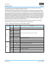
Note: In the PPC440x5 core, a single entry is established in the instruction shadow TLB (ITLB) and data
shadow TLB (DTLB) at reset with the properties described in Table 3-1. It is required that initialization soft-
ware insert an entry into the UTLB to cover this same memory region before performing any context synchro-


