


User’s Manual
Preliminary PPC440x5 CPU Core
cache.fm.
September 12, 2002
Page 99 of 589
4.1.2 Cache Locking and Transient Mechanism
Both caches support locking, at a “way” granularity. Any number of ways can be locked, from 0 ways to one
less than the total number of ways (64 ways for 32KB and 16KB cache sizes, 32 ways for the 8KB cache
size). At least one way must always be left unlocked, for use by cacheable line fills. Each way contains one
line from each set; that is, either 16 lines (512 bytes), for the 32KB cache size, or 8 lines (256 bytes), for the
16KB and 8KB cache sizes.
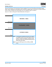
In addition, a portion of each cache can be designated as a “transient” region, by specifying that only a limited
number of ways are used for cache lines from memory pages that are identified as being transient in nature
by a storage attribute from the MMU (see Memory Management on page 133). For the instruction cache,
such memory pages can be used for code sequences that are unlikely to be reused once the processor
moves on to the next series of instruction lines. Thus, performance may be improved by preventing each
series of instruction lines from overwriting the rest of the “regular” code in the instruction cache. Similarly, for
the data cache, transient pages can be used for large “streaming” data structures, such as multimedia data.
As each piece of the data stream is processed and written back to memory, the next piece can be brought in,
overwriting the previous (now obsolete) cache lines instead of displacing other areas of the cache, which may
contain other data that should remain in the cache.
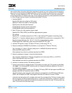
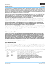
A set of fields in a pair of victim limit registers specifies which ways of the cache are used for normal
accesses and/or transient accesses, as well as which ways are locked. These registers, Instruction Cache
Victim Limit (IVLIM) and Data Cache Victim Limit (DVLIM), are illustrated in Figure 4-2. They can be written
from a GPR using mtspr, and can be read into a GPR using mfspr.
When a cache line fill occurs as the result of a normal memory access (that is, one not marked as transient
using the U1 storage attribute from the MMU; see Memory Management on page 133), the cache line to be
replaced is selected by the corresponding victim index field from one of the normal victim index registers
(INV0–INV3 for instruction cache lines, DNV0–DNV3 for data cache lines). As the processor increments any
of these normal victim index fields according to the round-robin mechanism described in Cache Line
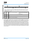
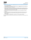
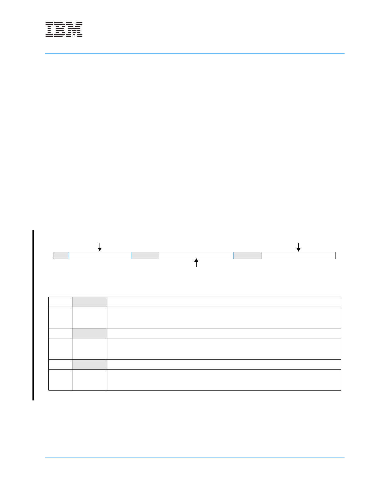
Figure 4-2. Instruction Cache Victim Limit (IVLIM) Data Cache Victim Limit (DVLIM)
0:1 Reserved
2:9 TFLOOR Transient Floor
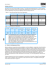
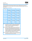
The number of bits in the TFLOOR field varies,
depending on the implemented cache size. See
Table 4-3,” on page -98 for more information.
10:12 Reserved
13:20 TCEILING Transient Ceiling
The number of bits in the TCEILING field varies,
depending on the implemented cache size. See
Table 4-3,” on page -98 for more information.
21:23 Reserved
24:31
NFLOOR
Normal Floor
The number of bits in the NFLOOR field varies,
depending on the implemented cache size. See
Table 4-3,” on page -98 for more information.
0 12 910 12 13 20 21 23 24 31
TFLOOR
NFLOOR
TCEILING