


User’s Manual
Preliminary PPC440x5 CPU Core
mmu.fm.
September 12, 2002
Page 153 of 589
is the Data Exception Address Register (DEAR), which provides the exception-causing address for Data TLB
Error and Data Storage interrupts. Finally, the Exception Syndrome Register (ESR) provides bits to differen-
tiate amongst the various exception types which may cause a particular interrupt type. See Chapter 6, “Inter-
rupts and Exceptions.” for more information on these mechanisms.
All of the TLB management instructions are privileged, in order to prevent user mode programs from affecting
the address translation and access control mechanisms.
5.9.1 TLB Search Instruction (tlbsx[.])
The tlbsx[.] instruction can be used to locate an entry in the TLB which is associated with a particular virtual
address. This instruction forms an effective address for which the TLB is to be searched, in the same manner
by which data storage access instructions perform their address calculation, by adding the contents of regis-
ters RA (or the value 0 if RA=0) and RB together. The MMUCR[STID] and MMUCR[STS] fields then provide
the process ID and address space portions of the virtual address, respectively. Next, the TLB is searched for
this virtual address, with the searching process including the notion of disabling the comparison to the
process ID if the TID field of a given TLB entry is 0 (see TLB Match Process on page 139). Finally, the TLB
index of the matching entry is written into the target register (RT). This index value can then serve as the
source value for a subsequent tlbre or tlbwe instruction, to read or update the entry. If no matching entry is
found, then the target register contents are undefined.
The “record form” of the instruction (tlbsx.) updates CR[CR0]
2
with the result of the search: if a match is
found, then CR[CR0]
2
is set to 1; otherwise it is set to 0.
When the TLB is searched using a tlbsx instruction, if a matching entry is found, the parity calculated for the
tag is compared to the parity stored in the TPAR field. A mismatch causes a parity error exception. Parity
errors in words 1 and 2 of the entry will not cause parity error exceptions when executing a tlbsx instruction.
5.9.2 TLB Read/Write Instructions (tlbre/tlbwe)
TLB entries can be read and written by the tlbre and tlbwe instructions, respectively. Since a TLB entry
contains more than 32 bits, multiple tlbre/tlbwe instructions must be executed in order to transfer all of the
TLB entry information. A TLB entry is divided into three portions, TLB word 0, TLB word 1, and TLB word 2.
The RA field of the tlbre and tlbwe instructions designates a GPR from which the low-order six bits are used
to specify the TLB index of the TLB entry to be read or written. An immediate field (WS) designates which
word of the TLB entry is to be transferred (that is, WS=0 specifies TLB word 0, and so on). Finally, the
contents of the selected TLB word are transferred to or from a designated target or source GPR (and the
MMUCR[STID] field, for TLB word 0; see below), respectively.
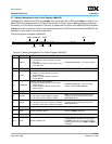
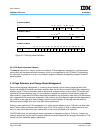
The fields in each TLB word are illustrated in Figure 5-5. The bit numbers indicate which bits of the
target/source GPR correspond to each TLB field. Note that the TID field of TLB word 0 is transferred to/from
the MMUCR[STID] field, rather than to/from the target/source GPR.
When executing a tlbre, the parity fields (TPAR, PAR1, and PAR2) are loaded if and only if the CCR0[CRPE]
bit is set. Otherwise those fields are loaded with zeros. When the tlbre is executed, If the parity bits stored for
the particular word that is read by the tlbre indicate a parity error, the parity error exception will be generated
regardless of the state of the CCR0[CRPE] bit.
When executing a tlbwe, bits in the source GPR that correspond to the parity fields are ignored, as the hard-
ware calculates the parity to be recorded in those fields of the entry.